Rope braking apparatus

a braking apparatus and rope technology, applied in the direction of hoisting equipment, load-engaging elements, thin material handling, etc., can solve the problems of unstable braking force, frequent checkup of hydraulic or pneumatic pressure, and degraded braking force, so as to prevent uneven wear of wire rope and stable braking force

Inactive Publication Date: 2015-03-10
BAE HOO GEUN
View PDF14 Cites 6 Cited by
  • Summary
  • Abstract
  • Description
  • Claims
  • Application Information

AI Technical Summary

Benefits of technology

[0016]Various embodiments of the prevent invention are advantageous in that pressurization of the wire rope solely by elastic force from elastic members, without using any hydraulic or pneumatic structure, solves the problems of degradation of braking force resulting from leakage of a fluid, environmental contamination resulting from use of the fluid, and the like. Furthermore, the structure of the pressurization unit itself and the structure of connection with the driving unit guarantee that the pressurization plate always moves along a straight line and pressurizes the rope, so that the pressure is applied across the entire pressurization plate, thereby securing stable braking force and preventing uneven wear of the wire rope.

Problems solved by technology

There have been extensive research and development on such rope braking apparatuses in line with stricter regulations for preventing accidents related to elevators, but most of such braking apparatuses, which usually employ a combination of hydraulic or pneumatic pressure and elastic force from springs, have problems in that the braking force may be degraded by leakage of the fluid, when hydraulic pressure is used, requiring frequent checkup of the hydraulic or pneumatic pressure.
As a result, there is a difference between a pressure applied to the upper portion of the rope and a pressure applied to its lower portion, making the braking force unstable, and there is also a possibility that friction force will be concentrated at a specific location on the rope, which may cause uneven wear of the rope or even cause the rope to break up.

Method used


Image

  • Rope braking apparatus
  • Rope braking apparatus
  • Rope braking apparatus

Examples


Embodiment Construction

[0026]Hereinafter, embodiments of the present invention will be described in detail with reference to the accompanying drawings so that those skilled in the art pertaining to the present invention can easily practice it. However, the present invention can be implemented in a number of different forms, and is not limited to the embodiments described below. The same components are given the same reference numerals throughout the description.

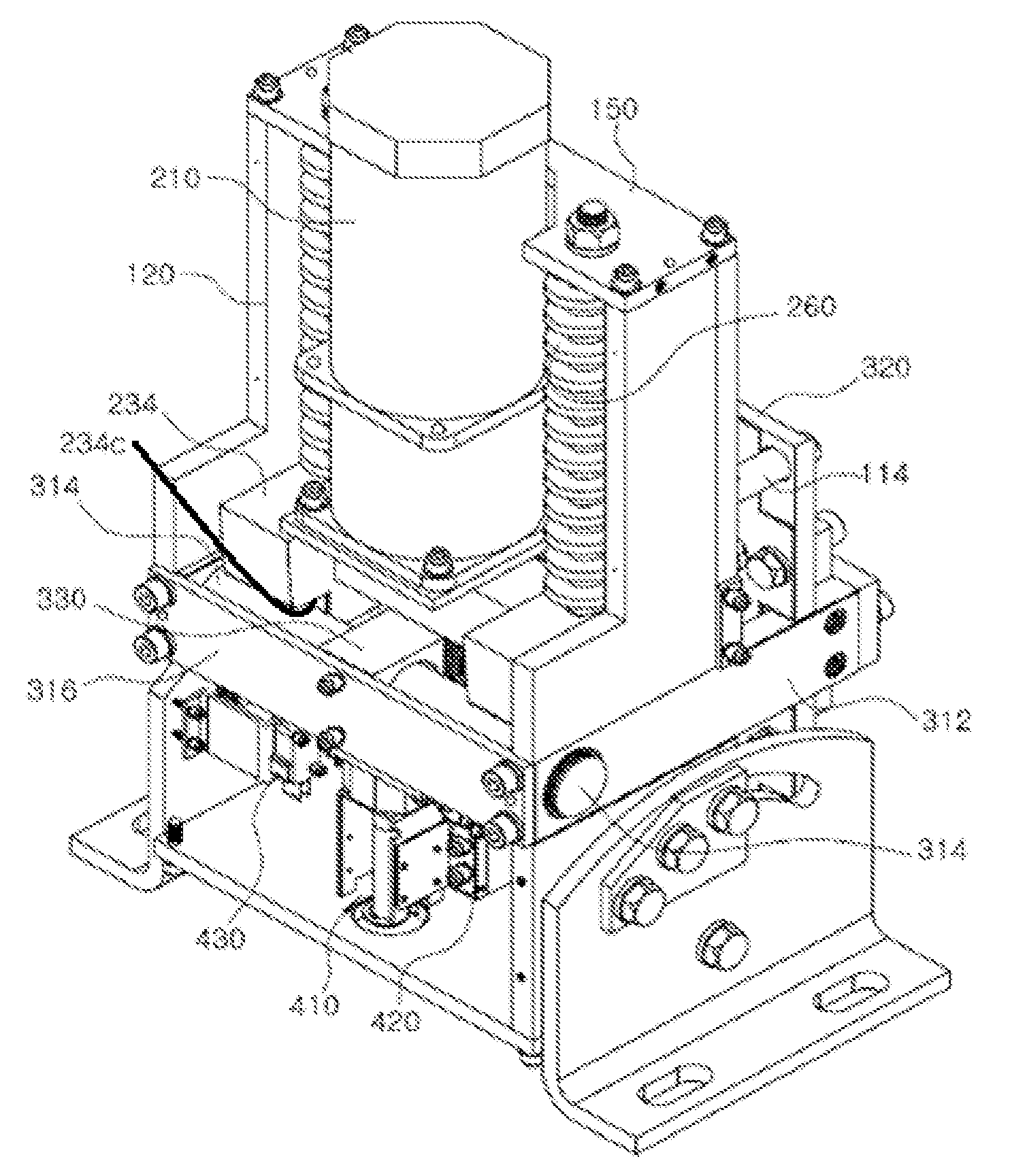
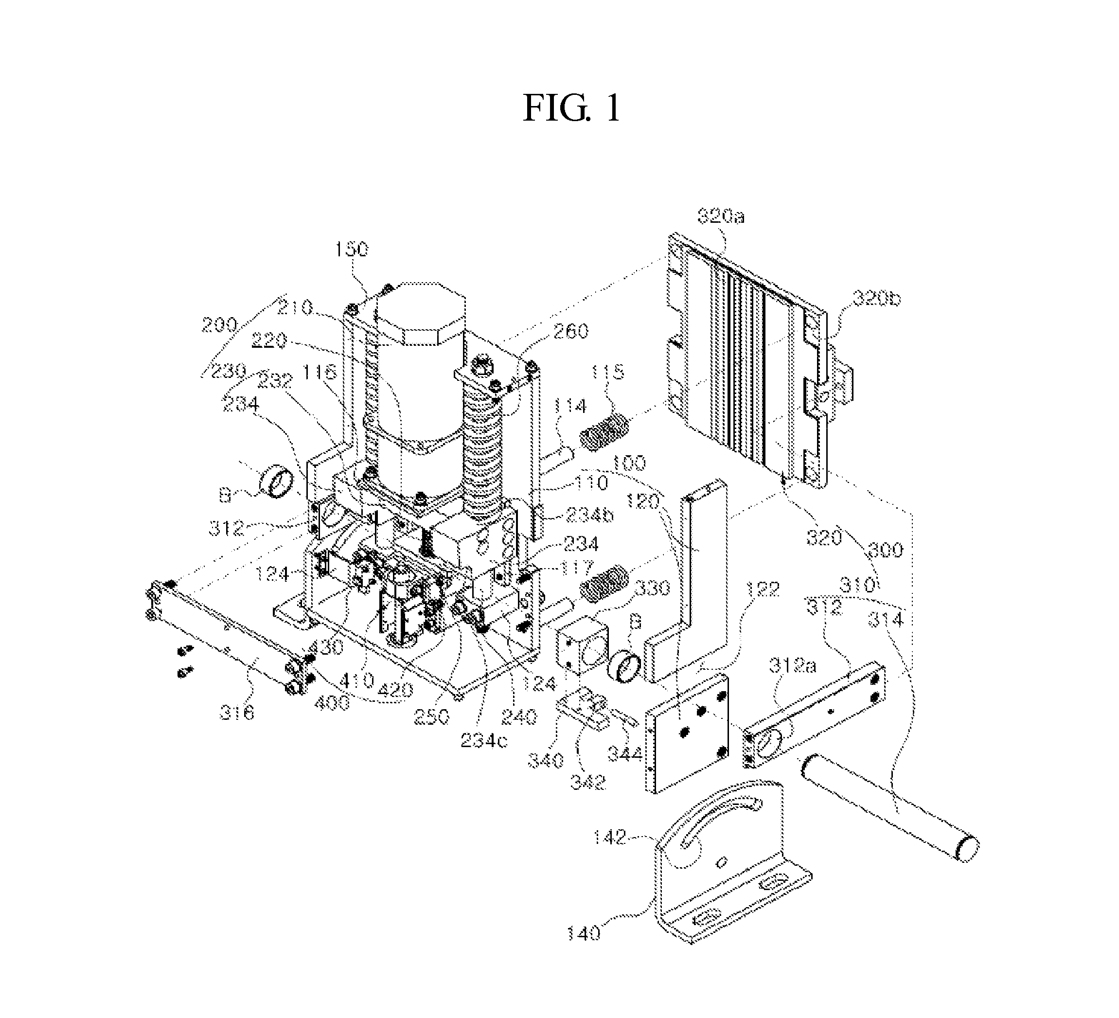
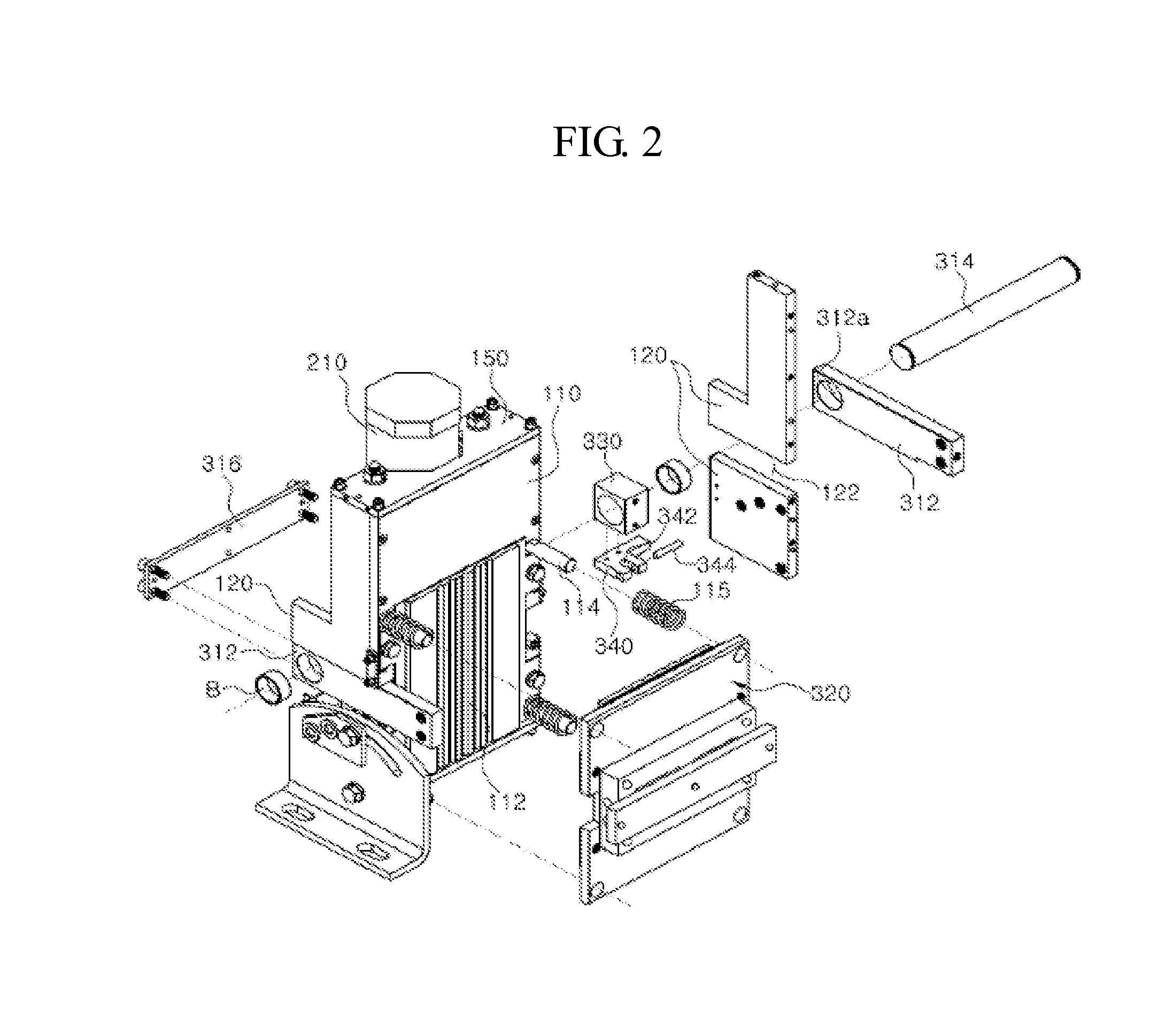
[0027]The rope braking apparatus according to the present invention includes, as illustrated in FIGS. 1 to 7, an installation body 100, a driving unit 200, a pressurization unit 300, and a movement control unit 400.

[0028]The installation body 100 serves as an overall case according to the present invention, which has an overall shape of a quadrangular box, and, more specifically, has lateral plates 120 installed on both sides of a rear plate 110 so that an installation space 130 is defined therein.

[0029]Both lateral plates 120 include fixing frames...


PUM


Abstract

The present invention relates to an elevator wire rope braking apparatus, and more particularly, to a rope braking apparatus which prevents partial abrasion of the wire rope while increasing braking efficiency by preventing a deviation in the pressure applied to the wire rope by a pressure plate moving in a straight line to apply pressure to the wire rope. Since the pressure application is based not on a hydraulic method but on a purely mechanical structure using only a spring elastic force, environmental pollution caused by hydraulic oil may be prevented and product cost may be reduced.

Description

CROSS REFERENCE TO PRIOR APPLICATION[0001]This application is a National Stage Patent Application of PCT International Patent Application No. PCT / KR2011 / 005998 (filed on Aug. 16, 2011) under 35 U.S.C. §371, which claims priority to Korean Patent Application No. 10-2010-0079331 (filed on Aug. 17, 2010), which are all hereby incorporated by reference in their entirety.TECHNICAL FIELD[0002]The present invention relates to a rope braking apparatus for pressurizing a wire rope during emergency braking in a hoist, a crane hoist, or an elevator, which is used to lift and lower an object tied to the wire rope.BACKGROUND ART[0003]An elevator used in a general building includes a winding machine installed on the building, a cage for carrying people, and a wire rope connecting the winding machine and the cage so that the cage is lifted or lowered by winding or unwinding the wire rope.[0004]Such an elevator is provided with a braking apparatus, which is used when the cage needs emergency brakin...

Claims


Application Information

Patent Timeline
Patent Type & Authority Patents(United States)
IPC IPC(8): B65H59/16B66B5/18B66B5/24B66C15/02B66D5/16F16D63/00
CPCF16D63/008B66B5/185B66B5/24B66C15/02B66D5/16
Inventor BAE, HOO-GEUN
Owner BAE HOO GEUN
Why Eureka
Try Eureka