Electromagnetic clutch

a technology of electromagnetic clutch and rotation stop plate, which is applied in the direction of mechanical actuator clutch, interlocking clutch, mechanical apparatus, etc., can solve the problems of high manufacturing cost and high cost of above-described conventional electromagnetic clutch, and achieve the effect of low cost and easy fabrication

Active Publication Date: 2015-03-10
OGURA CLUTCH CO LTD
View PDF12 Cites 3 Cited by
  • Summary
  • Abstract
  • Description
  • Claims
  • Application Information

AI Technical Summary

Benefits of technology

[0018]It is an object of the present invention to provide an electromagnetic clutch which reduces the manufacturing cost.
[0020]According to the present invention, since the bearing need not be fitted on the rotation stop member, neither burring work nor cutting work need be performed for the rotation stop member. Since the bearing can be retained by part of the rotation stop member, an abutment plate other than the rotation stop member need not be formed. An operation to weld the abutment plate to the rotation stop member can be omitted. The rotation stop member which regulates rotation of the field core is fabricated easily, so an electromagnetic clutch can be provided at low cost.

Problems solved by technology

The above-described conventional electromagnetic clutch 1 has a problem of high manufacturing cost.
As a result, the rotation stop plate 11 becomes expensive.

Method used


Image

  • Electromagnetic clutch
  • Electromagnetic clutch
  • Electromagnetic clutch

Examples


Embodiment Construction

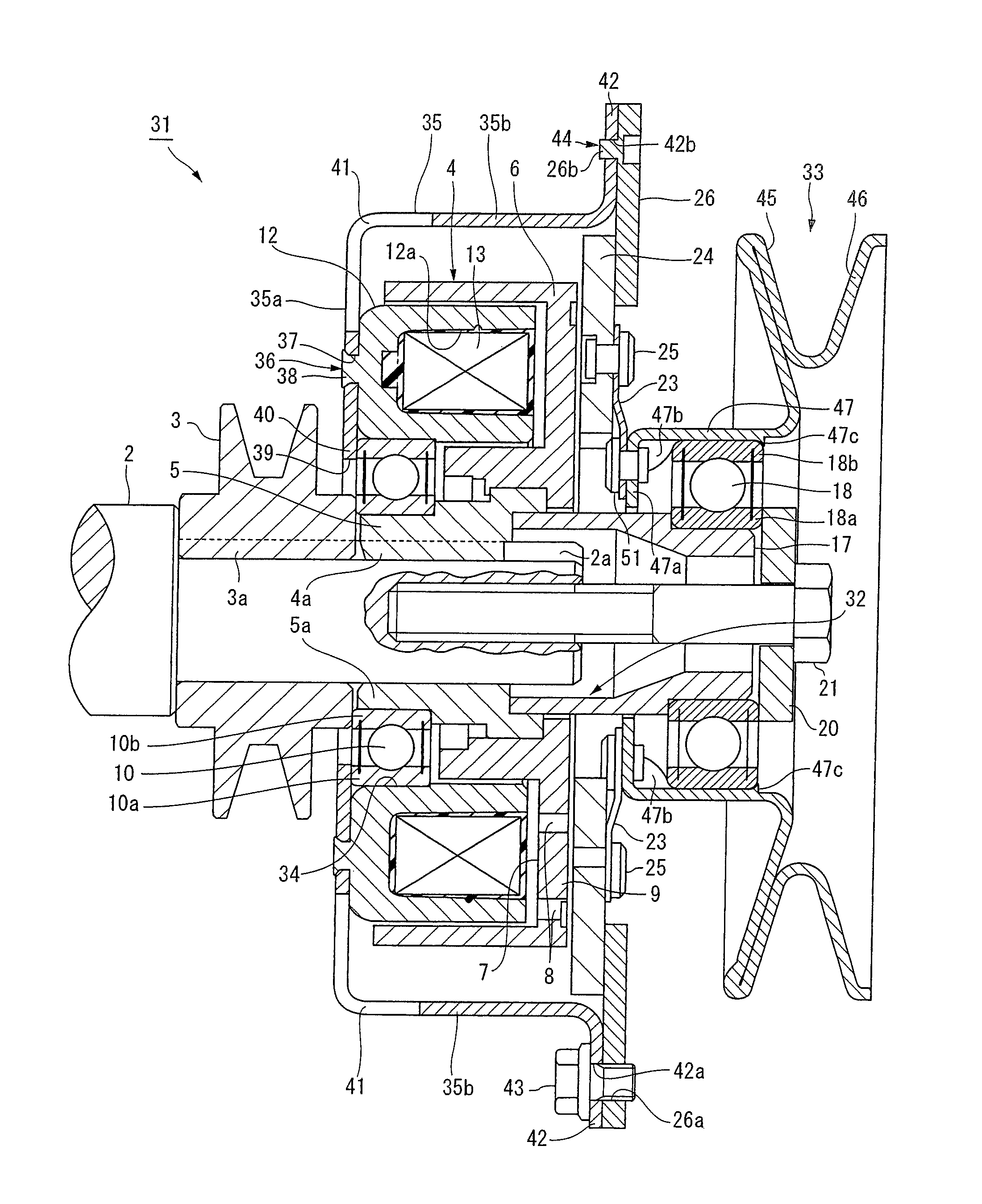
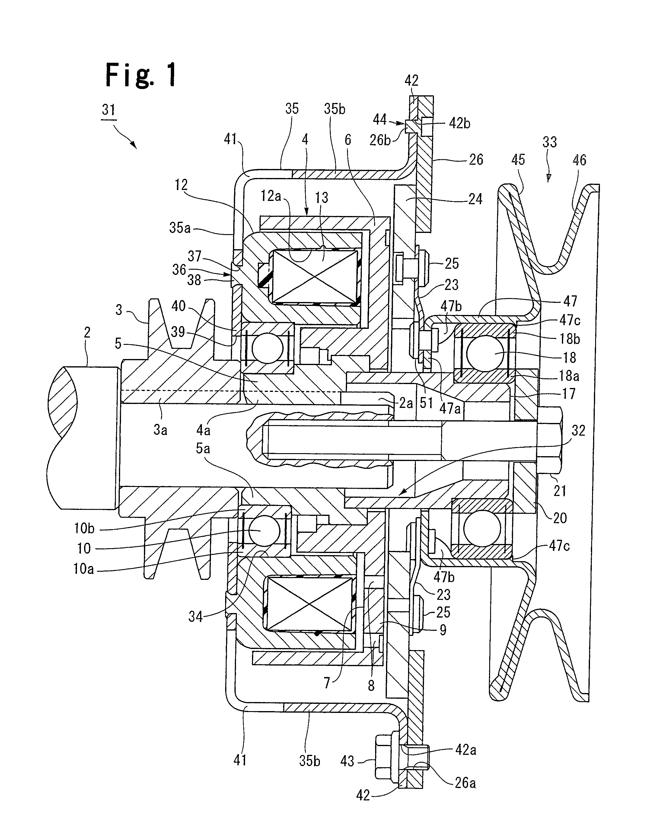
[0026]The present invention will now be described in detail with reference to the accompanying drawings. FIGS. 1 to 4 show an electromagnetic clutch according to an embodiment of the present invention. The same reference numerals as those in FIG. 5 denote the same or similar parts, and a detailed description thereof will be properly omitted. In the embodiment, for descriptive convenience, the distal end side (right side in FIG. 1) of an input shaft on which the electromagnetic clutch is mounted will be defined as the front side of the electromagnetic clutch, and the opposite side will be defined as the back side of the electromagnetic clutch.

[0027]An electromagnetic clutch 31 shown in FIG. 1 is switched between a coupling state in which rotation of a rotation transmission portion 32 (first rotation transmission portion) including a rotor 4 is transmitted to a rotation transmission portion 33 (second rotation transmission portion) via an armature 24, and a disconnection state in whic...


PUM


Abstract

An electromagnetic clutch includes a first rotation transmission portion, annular field core, rotation stop member, second rotation transmission portion, armature, and spring member. The annular field core is supported by the first rotation transmission portion via a first bearing. The first bearing is housed in a hollow portion of the field core and fitted on an inner circumferential surface of the field core. The rotation stop member includes a flat portion which is fixed to an end of the field core on a side opposite to the armature. The flat portion is formed integrally with a retaining piece which projects toward the hollow portion of the field core and faces the first bearing when viewed from the axial direction of the field core.

Description

BACKGROUND OF THE INVENTION[0001]The present invention relates to an electromagnetic clutch used as a power transmission device for a lawn mower, snow blower, and the like and, more particularly, to an electromagnetic clutch including a brake mechanism for preventing inertial rotation and idling on the output side after cutting off power transmission.[0002]A conventional electromagnetic clutch of this type has, e.g., a structure as shown in FIG. 5. As shown in FIG. 5, an electromagnetic clutch 1 is mounted on an input shaft 2 extending in the horizontal direction (right-and-left direction in FIG. 5). For descriptive convenience, the distal end side (right side in FIG. 5) of the input shaft 2 will be defined as the front side of the electromagnetic clutch 1, and the opposite side will be defined as the back side of the electromagnetic clutch 1.[0003]The input shaft 2 is driven to rotate by an engine (not shown), a motor (not shown), or the like. A pulley 3 and a rotor 4 of the electr...

Claims


Application Information

Patent Timeline
Patent Type & Authority Patents(United States)
IPC IPC(8): B60W10/02B60W10/18F16D67/06F16D27/04
CPCF16D27/04F16D27/112F16D27/14F16D67/06
Inventor TAKAHASHI, TOSHIOYOSHIHARA, HIROYASUARAI, MIYUKI
Owner OGURA CLUTCH CO LTD
Why Eureka
Try Eureka