Method for enhanced aerobic activity and bio-mat control for onsite wastewater disposal systems

a biomat and aerobic activity technology, applied in biological water/sewage treatment, filtration separation, separation processes, etc., can solve the problems of bio-mat thickening much faster, premature clogging of disposal area with anaerobic sludge, and failure of the disposal area, so as to improve aerobic activity and reduce the effect of clogging and clogging of the disposal area

Active Publication Date: 2015-03-10
JRL INNOVATIONS
View PDF53 Cites 5 Cited by
  • Summary
  • Abstract
  • Description
  • Claims
  • Application Information

AI Technical Summary

Benefits of technology

[0011]The present invention is utilized for controlling and maintaining the aerobic environment under septic disposal areas, allowing for rejuvenation of clogged disposal areas, and providing enhanced aerobic activity in the disposal areas with restricted aerobic activity and/or limited permeable surface above the secondary treatment areas. This invention allows for low rate aeration, and high rate air wash...

Problems solved by technology

Where aerobic conditions are not typically maintained, the bio-mat will thicken much more quickly and failure of the disposal area will result quicker than a typical aerobic state disposal bed.
The effluent of a septic tank contains substantial anaerobic bacteria, and unless the disposal area is maintained in an aerobic state, the anaerobic bugs will flourish and the bio-mat will tend to thicken and the disposal area will clog prematurely with anaerobic sludge.
If the disposal area is affected by site specific conditions which do not allow for a shallow disposal bed covered with grass, anaerobic condition can occur.
In cases where disposal areas are adversely affected b...

Method used


Image

  • Method for enhanced aerobic activity and bio-mat control for onsite wastewater disposal systems
  • Method for enhanced aerobic activity and bio-mat control for onsite wastewater disposal systems
  • Method for enhanced aerobic activity and bio-mat control for onsite wastewater disposal systems

Examples


Embodiment Construction

[0030]FIGS. 1-12 show an aeration system 50 of the present invention for disposal areas.

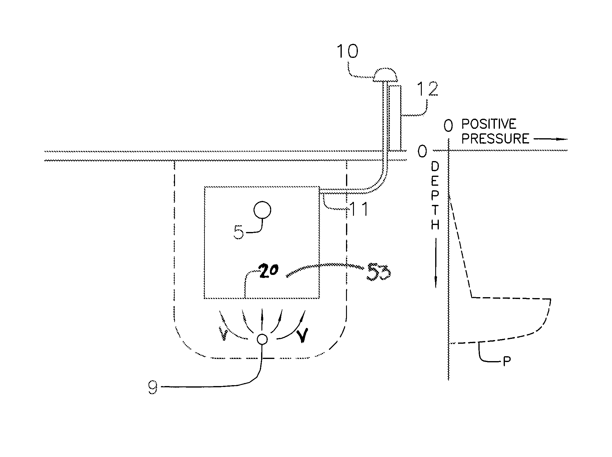
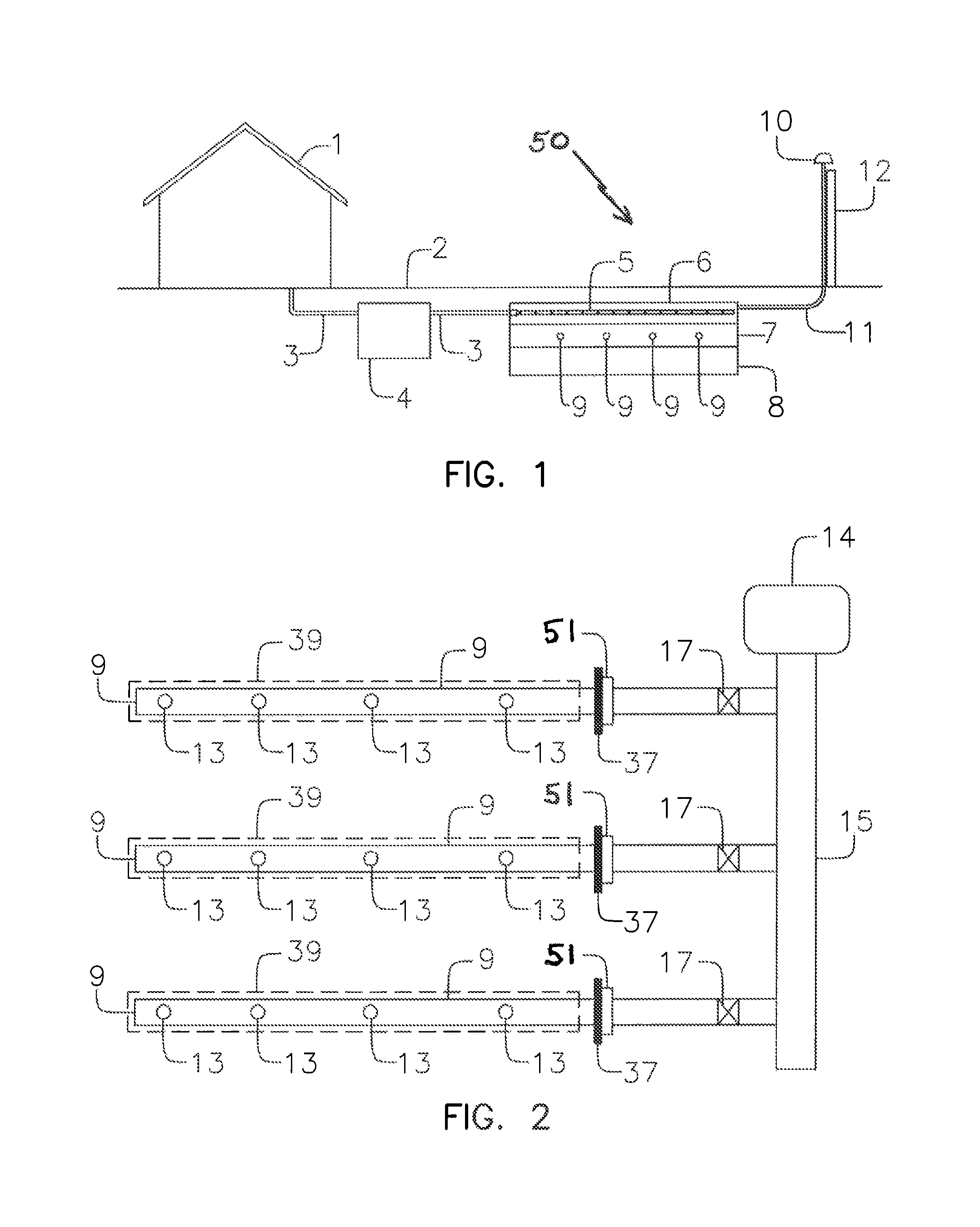
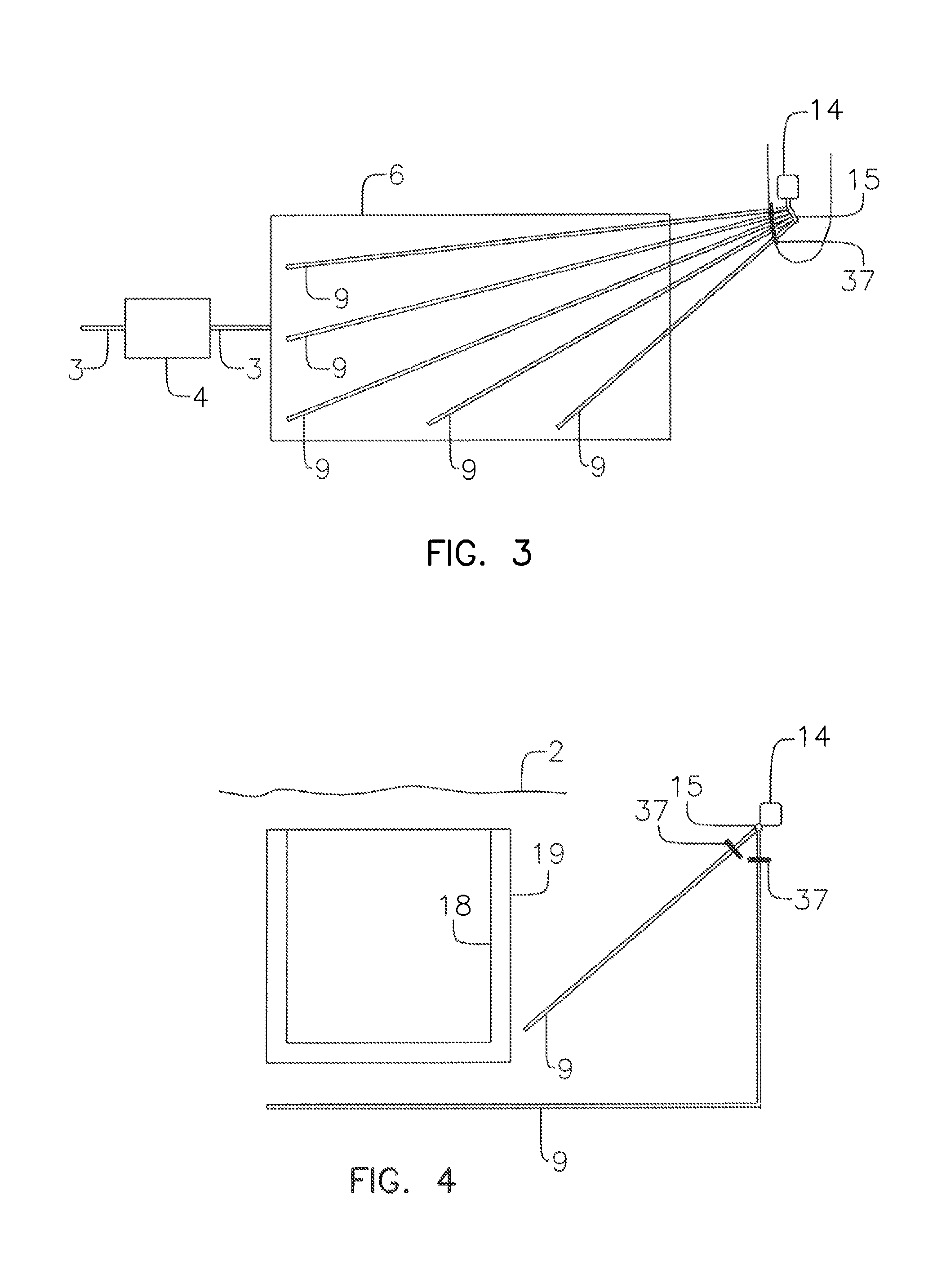
[0031]FIG. 1 shows septic system with a method for enhanced aerobic activity for a disposal area 6. A disposal area 6 includes, but is not limited to, disposal bed, seepage pit and the like. The septic system includes a source 1 of wastewater connected to connection pipes 3 which are located below ground level 2. The source of wastewater fed to the disposal areas 6 can be from a variety of sources as know in the art. The wastewater includes any known wastewater, such as storm or sewer water as known in the art. The connection pipes 3 connect the source 1 of the wastewater to a primary treatment septic tank and / or aerobic treatment and / or pump tank 4. The connection pipes 3 also connect the tank(s) 4 to wastewater disposal laterals 5 which are perforated lateral pipes or infiltration chambers which allow the wastewater to escape to the disposal area 6. The wastewater disposal laterals 5 can be sur...


PUM

PropertyMeasurementUnit
Flow rateaaaaaaaaaa
Diameteraaaaaaaaaa
Lengthaaaaaaaaaa

Abstract

The present invention provides an aeration lateral system designed to be site specific for new septic disposal areas or retro fitting to existing septic disposal areas to break up the biological clogging sludge mat at the interface of the wastewater and imported sand or native soil fill under or adjacent to disposal areas of a typical septic system. The lateral system provides uniform or other site specific distribution of fluids about the bio-mat of a wastewater disposal area, with lateral spacing and hole spacing varying based on the type of disposal area being utilized. The lateral system can also be utilized to provide continuous low volume air supply system to a wastewater disposal area or peat filter module. The air lateral installation includes methods to minimize airflow disturbance of the soil and methods to prevent air leakage.

Description

CROSS-REFERENCE TO RELATED APPLICATION[0001]This application claims priority to U.S. Provisional Application No. 61 / 377,178, filed Aug. 26, 2010, the contents of which are incorporated by reference herein.FIELD OF THE INVENTION[0002]This invention relates to enhance aeration of an onsite wastewater disposal area located after a primary treatment (settling tank / septic tank / aerobic tank).BACKGROUND OF THE INVENTION[0003]A typical septic system includes a septic / aerobic tank or septic / aerobic tank and pump tank where primary treatment of wastewater takes place. The effluent wastewater then flows to a disposal area, buried in the soil, for secondary treatment and disposal into the ground. In conventional septic systems, the disposal area can include a disposal bed or trenches with stone and pipe laterals, or a disposal bed or trenches with infiltration chambers, or seepage pits. Secondary treatment of wastewater will typically naturally occur at the interface between the disposal area a...

Claims


Application Information

Patent Timeline
IPC IPC(8): C02F3/00
CPCC02F3/046C02F3/109C02F3/20C02F3/288C02F2209/38C02F3/307Y02W10/10C02F3/06C02F2203/006C02F3/201C02F2303/22C02F2303/20
Inventor EMR, ROY
Owner JRL INNOVATIONS
Why Eureka
Try Eureka