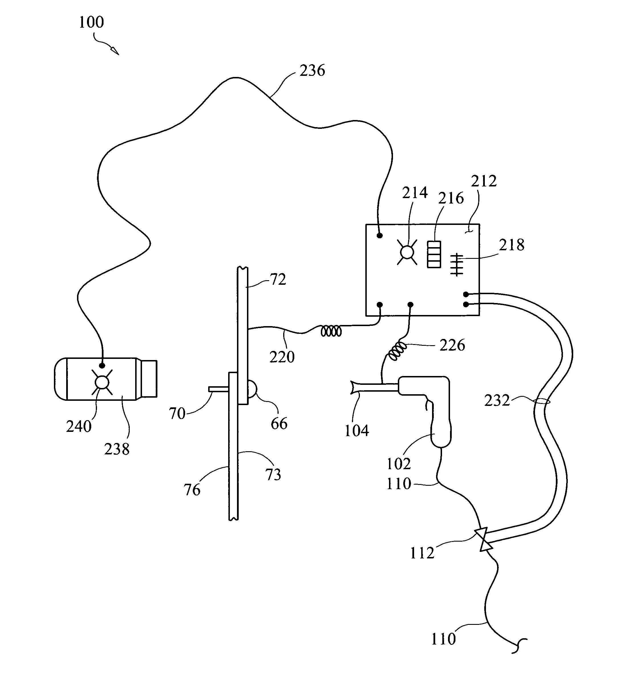
[0039]One object of preferred embodiments of the invention is to measure the height of the formed rivet head during the rivet driving process and through a feedback control process disable or stop the rivet gun the moment the rivet head achieves the desired set tolerance. In this embodiment, an automated control process allows both operators to focus on holding their tools orthogonal to the work surface and not be concerned about under-driving or over-driving the rivet. Another object of preferred embodiments of the invention is to provide a means for communicating the stage of the rivet driving process to both rivet-gun and bucking operators by means of light, e.g., light-emitting diode (LED) indicators, with at least one LED located on or near the bucking bar and at least one LED located on or near the rivet gun. By detecting the switch states of one or more switches, the control system operates the LED indicator lights to sequentially signal the operators and thus guide them through each sequential stage of the rivet setting cycle.
[0040]It is yet another object of preferred embodiments of the invention to prevent inadvertent damage to the airframe by using a control system to disable the rivet gun when not needed and enable the rivet gun only when both the rivet-gun operator and bucker have signaled (by LED lights via a microprocessor detecting switch states) that they are ready for the rivet driving stage of a rivet setting cycle.
[0042]It is yet another object of preferred embodiments of the invention to perform data logging in microprocessor memory of the measured rivet driven head height after the rivet has been set for Quality Assurance and Quality Control verification purposes. It is yet another object of preferred embodiments of the invention to use a disclosed plunger mechanism to press pieces of joined work pieces together by applying compression spring force to the work surface during the rivet setting process. Additionally, the plunger mechanism in this preferred embodiment of this invention also forms a shroud around the rivet head and thus serves to prevent the bucking tool from sliding off the formed rivet head during the rivet driving stage. This reduces a damage event condition or opportunity of the rivet gun hammering on a rivet this is not backed by a bucking bar and thus causing damage to the airframe or substructure work. Furthermore, the plunger mechanism also helps the bucker maintain orthogonal alignment of the bucking tool relative to the work by holding the spindles feet of the plunger flush against the work during the rivet driving cycle.
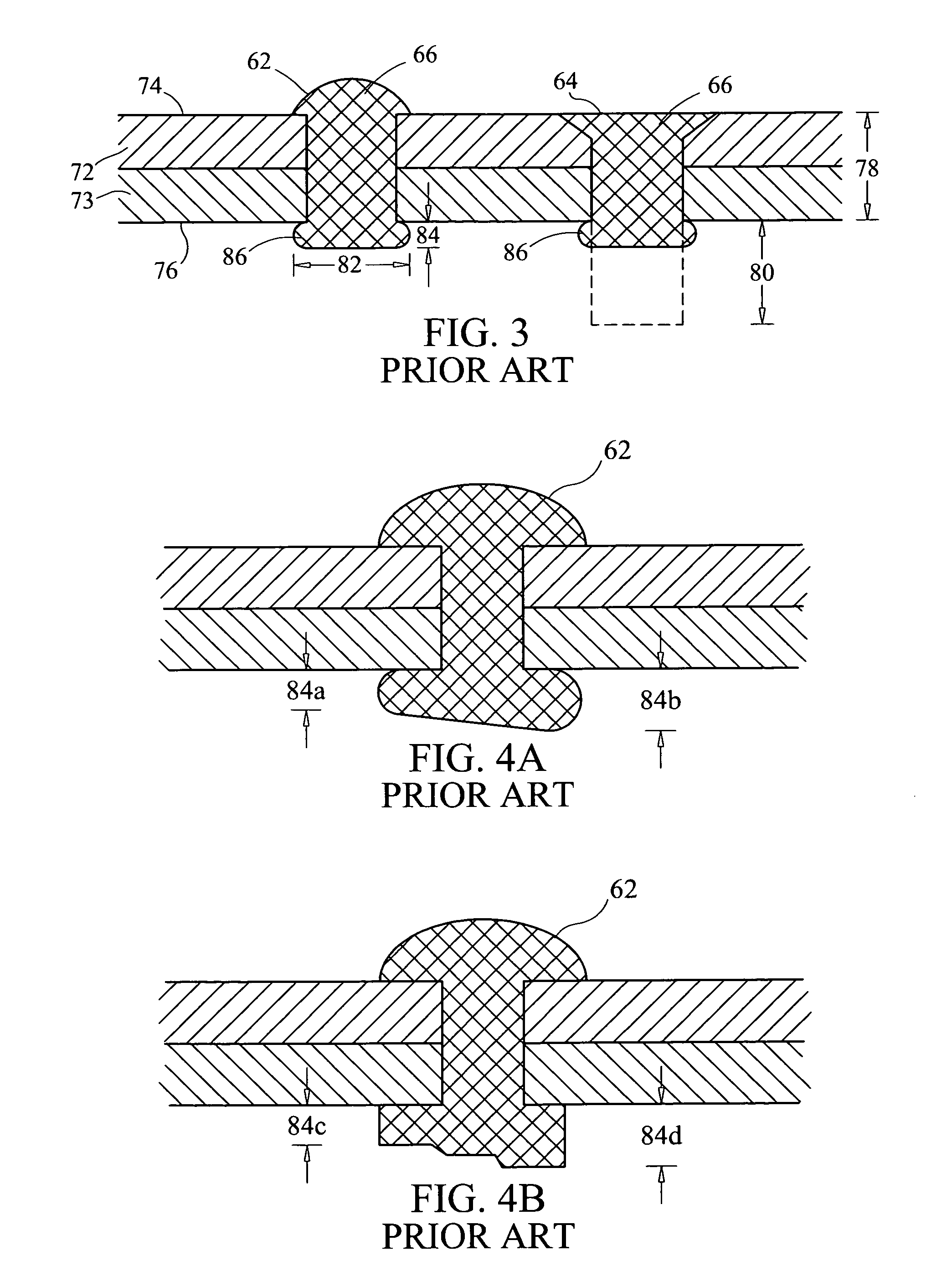
[0044]While as previously stated preferred embodiments of the invention eliminate under-driving the rivet and consequently prevents a plurality of hammering sessions; it is yet another object of preferred embodiments of the invention to maximize set rivet material strength. During the rivet driving stage, the rivet shank undergoes plastic deformation; the shank-end becomes the driven head and forms into a mushroom shape and the shank also simultaneously expands. If the gun force is set too low, then excessive rivet gun blows or impacts are required to set the rivet; this causes the rivet material to fatigue or work harden resulting in reduced material strength of the rivet and therefore reduced rivet holding strength. Ideally to achieve the best rivet properties, rivets should be set with a minimum number of impacts but excessive rivet gun force is difficult for operators to control while simultaneously maintaining tool alignment orthogonal to the work surface. In this embodiment, therefore, the control system provides feedback for optimal air flow and / or air pressure supplied to the gun based on the number of impacts and / or the driving stage time to set a rivet. In other words, the feedback system determines if the rivet gun impact force should be increased or decreased while also keeping the impacting force within acceptable operator-tool-control limits. The rivet setting time interval measurement begins when the rivet driving stage starts and ends when the driven head achieves optimum tolerance (when a measuring threshold has been reached). The number of impacts is preferably counted by assessing the digital signature to debounce the signals from the bucking bar contact with the rivet, as detected by a momentary break or switching in a circuit by a computer or microprocessor. Alternately, an accelerometer or other impact sensor attached to the rivet gun, bucking bar or air supply line may be used to count the number of rivet-driving-stage impacts. Therefore, either an accelerometer or signal debouncer may serve as an impact sensor. Rivet setting time is a measurement of the driving stage time by a microprocessor. The control system then indicates to the operator to increase or decrease the impact force via flow or pressure changes or alternately automatically makes this adjustment by controlling the air regulator settings or other settings for the rivet gun. Any type of communication such as LEDs, LED light bars or liquid crystal displays (LCDs) may be used to notify the rivet gun operator of recommended air-pressure regulator setting changes.
[0045]In an alternate embodiment of the invention, the operator provides microprocessor inputs such as the size of the rivet being driven and the total joined sheathing material thickness into the microprocessor's memory via any type of input device such as a keypad. This allows the microprocessor to determine the optimal number of impacts needed for the job in order to produce the highest strength rivets and also determines the optimal tolerance threshold for the formed rivet head height (where analogue sensors are employed). Determining rivet size may also be achieved by measuring the protruding shank length after a rivet has been inserted into a hole. Those skilled in the art will appreciate that a control approach disclosed herein, coupled with real-time or near-real-time measurement of the upsetting rivet head, may also be used to set solid shank rivets at a specified location on a stress-strain curve to maximize rivet fastener strength and durability. Furthermore, with accurate and precise measurement systems coupled to real-time feedback control incorporated into the invention, achieving “ideal” or very low standard deviations (at, near or better than “six sigma”) for any desired rivet set objective is possible. Furthermore, even higher rivet set tolerance (higher standard deviation) is desired to more precisely control the set rivet product. Achieving extremely high tolerance levels may involve feedback and / or feed forward control strategies.
[0068]In another illustrative embodiment, the invention is a method for fastening a rivet having a shank and a shank end, in a work piece having a work surface with a system comprising a rivet driver, a controller that is operative to enable and disable the rivet driver, a microprocessor that is operative to control controller, a plunger having a contact point, a load source that is operative to urge said contact point to maintain contact with the work surface, an anvil having an anvil face, and a first sensor that is operative to sense the distance between the work surface and said anvil face, said method comprising: placing the plunger against the work surface and applying a load to the plunger that is operative to load the load source until the anvil face contacts a shank end; driving the rivet with the rivet driver; with the first sensor, sensing the distance between the work surface and the anvil face and generating a first input signal related to such distance; with the microprocessor, receiving said first input signal from the first sensor, determining when said distance is substantially equal to a desired rivet head height, and then actuating the controller to disable the rivet driver. In another embodiment, the system further comprises a second sensor, and said method further comprises: with the second sensor, generating a second input signal when the anvil face first contacts the shank end; and with the microprocessor: receiving said second input signal and generating a second output signal that indicates that said anvil face is in first contact with the shank end; or, receiving said second input signal and determining a desired rivet head height based on said distance. In another embodiment, the method further comprises applying a load to the work piece with said plunger, said load being operative to minimize any air gap existing between a plurality of work pieces.