Stent, microcatheter, braiding apparatus for continuous hoselike body, and process for manufacturing stent

a technology of hoselike body and micro-catheter, which is applied in the field of stent, micro-catheter, and braiding apparatus for continuous hoselike body, which can solve the problems of inability to guide the stent into the blood vessel inability to achieve sufficient blocking of blood flow from the blood vessel into the dilation, and inability to insert the conventional stent in a bunched state into the microcatheter for guidance of th

Active Publication Date: 2015-03-17
IR MEDICAL ATELIER
View PDF25 Cites 21 Cited by
  • Summary
  • Abstract
  • Description
  • Claims
  • Application Information

AI Technical Summary

Problems solved by technology

The conventional stent, however, has a defect in that sufficient blocking of blood flow from the blood vessel into the dilation cannot be achieved because of small interspaces opening between the thin wires of the stent once the stent that has been gathered finely by the pull in the longitudinal direction is inserted into the catheter, guided into the blood vessel, and pushed out of an extremity of the catheter in an area of development of the dilation so as to cause resilient restoration to the original hoselike state until the restored stent is set in a position such that the opening of the dilation is closed.
A stent having a multiplicity of thin wires of elastic metal arranged closely and braided into a hoselike body for improvement of blocking blood flow into the dilation has had a drawback of being prone to closing collateral vessels in the vicinity of a dilation even though it may be capable of blocking blood flow into the dilation when being guided likewise to an area of development of the dilation in a blood vessel and set in a position such that an opening of the dilation may be closed.
There has been proposed a stent in which a multiplicity of thin wires of elastic metal braided into a hoselike body with interspaces provided between the wires and in which a flexible synthetic resin film is stuck in a cylindrical shape on a portion of the hose having a length required for closure of an opening of dilation, whereas bulkiness of the synthetic resin film may make it impossible to insert the conventional stent in a bunched state into a microcatheter for guidance of the stent into a blood vessel.

Method used


Image

  • Stent, microcatheter, braiding apparatus for continuous hoselike body, and process for manufacturing stent
  • Stent, microcatheter, braiding apparatus for continuous hoselike body, and process for manufacturing stent
  • Stent, microcatheter, braiding apparatus for continuous hoselike body, and process for manufacturing stent

Examples


embodiment 1

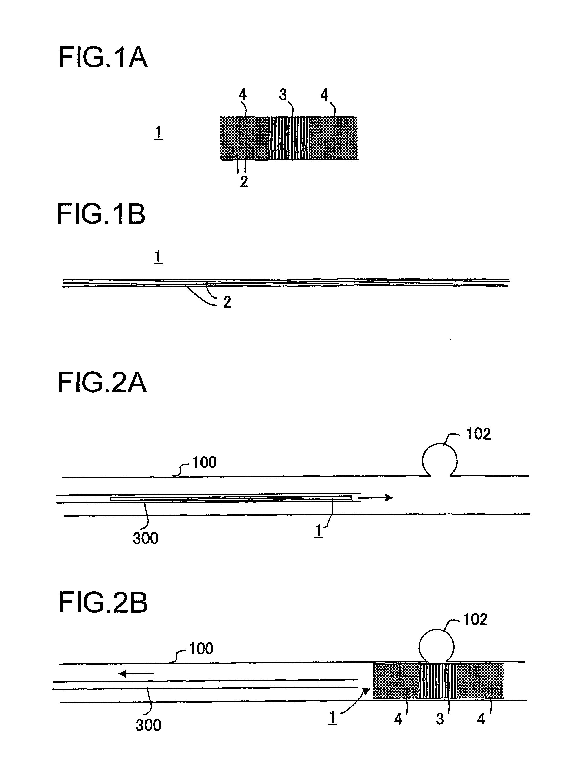
[0071]In a stent 1 of FIG. 1A, alternate twelve out of superelastic thin wires 2 (with a diameter of 0.03 mm) of nickel-titanium alloy are wound in the shape of a left-handed helix around a circumferential surface of a cylinder, the remaining twelve are wound in the shape of a right-handed helix, the left-handed thin wires 2 and the right-handed thin wires 2 are obliquely intersected like a plain weave and braided into a hoselike body having a specified length, an intermediate portion of the hoselike body is formed into a thin wire densely braided superelastic hose portion 3 in which mutually neighboring thin wires are in contact with each other or close to each other with a minute interspace, and both side portions thereof are formed into thin wire coarsely braided superelastic hose portions 4 in which mutually neighboring thin wires are provided with an interstice allowing passage of blood flow.

[0072]Referring to actual manufacturing processes, twenty-four thin wires 2 of titanium...

embodiment 2

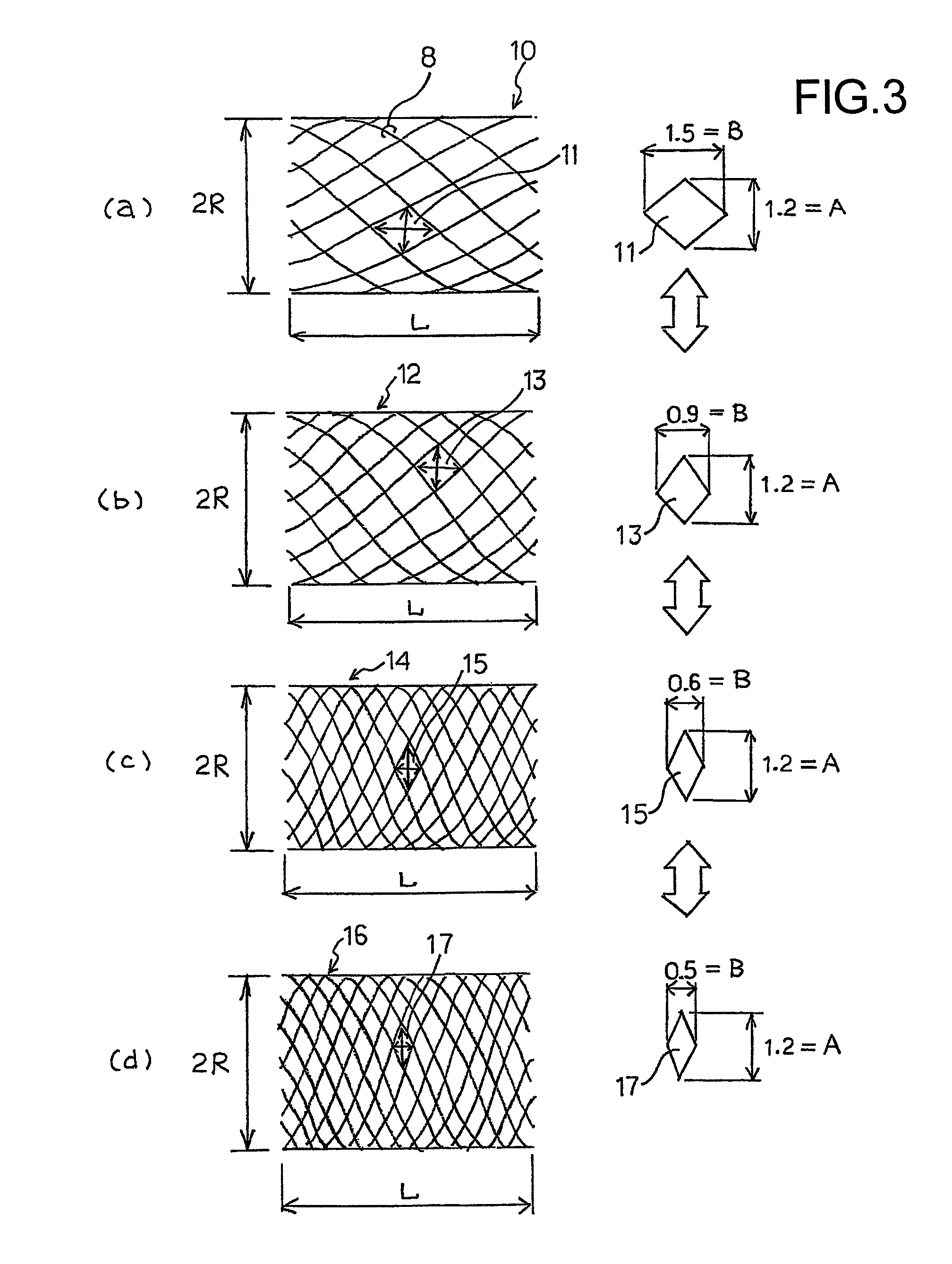
[0078]Thin wires composed of shape memory material are fed into and braided by the knitting machine as described above, and then a hoselike body having reticulated gaps in the shape of diamond is formed as shown in FIG. 3. FIG. 3 show change in the diamond-shaped reticulated gaps in the hoselike body with respect to change in velocity of the conveyance in the knitting machine in a direction of braiding, that is, braiding velocity in the longitudinal direction of the hoselike body. The braiding velocity changes from high to low along a direction from FIG. 3(a) at top to FIG. 3(d) at bottom.

[0079]Referring to FIG. 3(a) at the top of FIG. 3, a radius of the hoselike body 10 is designated by reference character R and a length thereof in the longitudinal direction is designated by character L. In this example, the thin wires 8 described with reference to FIGS. 1, 2 are replaced by those having a diameter of 50 μm, and twelve thin wires 8 are loaded in the knitting machine for each of the...

embodiment 3

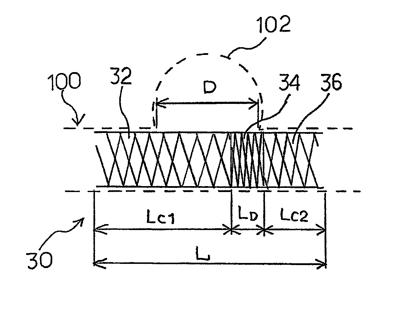
[0087]FIG. 4 is a diagram showing a configuration of a stent 20 suitable for blood vessel dilation 102 in a blood vessel 100 with an opening having a size D. In the stent 20, a thin wire coarsely braided hose portion 22 having coarse reticulated gaps, a thin wire densely braided hose portion 24 having dense reticulated gaps, and a thin wire coarsely braided hose portion 26 having coarse reticulated gaps are formed in the stated order along the longitudinal direction of the stent 20. An overall length L of the stent 20 in the longitudinal direction is preferably about two times the size D of the opening of the blood vessel dilation 102 provided that the size D is known, for example.

[0088]As described above, the size B of the reticulated gaps of the thin wire densely braided hose portion 24 along the longitudinal direction of the stent 20 is preferably 0.1 mm or smaller. A length LD of the thin wire densely braided hose portion 24 along the longitudinal direction of the stent 20 is pr...


PUM


Abstract

A stent (1) comprising a hoselike body obtained by braiding a multiplicity of thin wires (2) of superelastic metal into plaited form. In the longitudinal intermediate portion of the hoselike body, mutually neighboring individual thins wires (2) of superelastic metal are in contact with each other or close to each other with a minute interspace and are formed into a thin wire densely braided hose portion (3) with a length needed to block any opening of blood vessel dilation. At both side portions thereof, mutually neighboring individual thin wires (2) of superelastic metal are formed into a thin wire coarsely braided hose portion (4) provided with an interstice allowing passage of blood flow. The hoselike body when pulled in the longitudinal direction causes the individual thin wires (2) of superelastic metal to stretch into fine gathering, and when released from pulling can make resilient restoration to the original hoselike body.

Description

TECHNICAL FIELD[0001]The invention relates to a stent having a configuration that can be placed in a blood vessel and that is capable of closing at least part of an opening of a blood vessel dilation such as aneurysm and varix, blocking blood from flowing into the dilation, and thereby preventing the dilation from rupturing, a microcatheter for holding the stent, a continuous hoselike body braiding apparatus for forming the stent, and a process for manufacturing the stent.BACKGROUND ART[0002]For treatment against blood vessel dilation that is a disease of the artery or vein, as described in Non-Patent Document 1, there have been known a coil inserted into the blood vessel dilation, a stent inserted into a main blood vessel having the blood vessel dilation, and the like that are used in combination with a catheter, a balloon and the like.[0003]As such a type of stent, there has conventionally been known a stent having a multiplicity of thin wires of elastic metal braided into a hosel...

Claims


Application Information

Patent Timeline
Patent Type & Authority Patents(United States)
IPC IPC(8): A61F2/06A61F2/90A61F2/95A61F2/966
CPCA61F2/95A61F2/90A61F2250/0017A61F2002/9522A61F2250/0018A61F2002/823D04C1/02D04C3/06D04C3/10A61F2/9522D10B2509/06
Inventor MURAYAMA, YUICHI
Owner IR MEDICAL ATELIER
Why Eureka
Try Eureka