
Ammonia generating and delivery apparatus

a technology of ammonia generating and delivery apparatus, which is applied in the direction of machines/engines, process and machine control, instruments, etc., can solve the problems of high energy consumption, delivery rate control problems, and difficulty in accurately delivering solid reductants as required

Active Publication Date: 2015-03-17
QI BAOHUA
View PDF1 Cites 9 Cited by
  • Summary
  • Abstract
  • Description
  • Claims
  • Application Information

AI Technical Summary

Benefits of technology

This approach allows for accurate and efficient ammonia delivery with reduced energy consumption and improved control over the ammonia releasing rate, enhancing system stability and safety.

Problems solved by technology

Due to safety concerns and difficulties in transportation and storage, in SCR systems, normally ammonia is generated from a precursor, such as urea, rather than being used directly.
However a hindrance for using solid reductants is the issues in delivering the reductant, including high energy consumption, pressure variation, and delivery rate control problems.
These issues make it difficult to deliver solid reductants accurately as required.
Since when heating the solid reductant, all reductant in the container is heated, high heating power is needed and it is difficult to control the pressure in the container, especially when the quantity of reductant is large, due to time delay caused by heat transfer.
Changes in pressure affect ammonia delivery accuracy, especially when a feedback control, which may significantly increase system complexity and cost, is not available.
And overly high pressure may also create safety concerns.

Method used


Image

  • Ammonia generating and delivery apparatus
  • Ammonia generating and delivery apparatus
  • Ammonia generating and delivery apparatus

Examples


Embodiment Construction

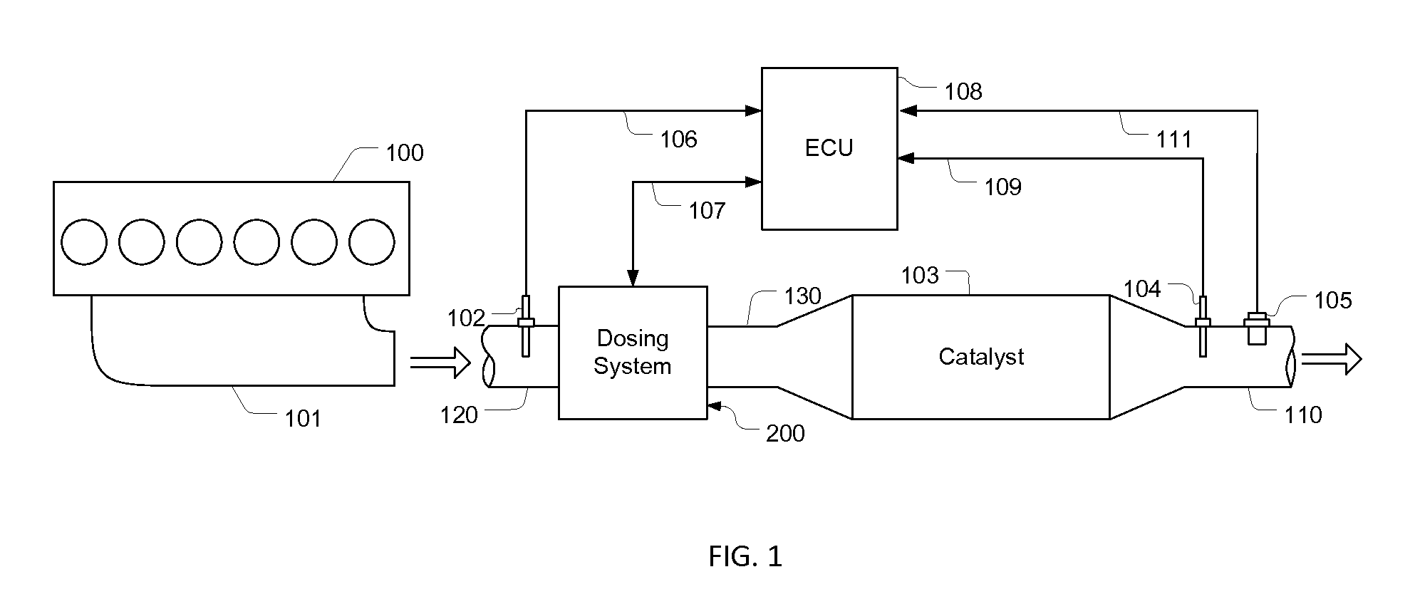
[0031]Referring to FIG. 1, in an engine exhaust gas treatment system, an exhaust gas generated by an engine 100 enters a passage 120 through a manifold 101. The passage 120 is fluidly connected to a dosing system 200, which is controlled by an ECU (Engine Control Unit) 108 through signal lines 107. Inside the dosing system 200, reductant is delivered and mixed with the exhaust gas. And through a passage 130, the result mixed air flows into a catalyst 103, where reductant reacts with the NOx in the exhaust gas and reduces it. On the passage 120, a temperature sensor 102 is used to measure the temperature of the exhaust gas upstream from the catalyst 103 and the sensing signals are sent to the ECU 108 via signal lines 106. A temperature sensor 104 installed on a tail pipe 110, which is fluidly connected to the catalyst 103, is used to measure the exhaust gas temperature downstream from the catalyst 103, and the sensing signals are obtained by the ECU 108 through signal lines 109. On t...


PUM


Abstract

An ammonia generating and delivery apparatus generating ammonia by heating a precursor material with a heating device controlled by a temperature pulse controller which receives commands from a pressure controller, and delivering ammonia with a flow rate controlled by a three-stage PWM controller. The temperature pulse controller is used in a first feedback loop to create a temperature pulse sequence at a surface of the heating device. A pressure controller in a second feedback loop provides duty-cycle commands to the temperature pulse controller, while in delivering ammonia, effects of pressure variation to delivery accuracy are compensated in the three-stage PWM controller, which includes a flow-rate feedback loop. The ammonia generating and delivery apparatus can also include two containers, in which the precursor material in one container is charged and discharged according to the capability of the other container in generating ammonia.

Description

[0001]This present application claims priority from U.S. provisional application No. 61 / 803,751 having the same title as the present invention and filed on Mar. 20, 2013.CROSS-REFERENCE TO RELATED APPLICATIONS[0002]Not ApplicableSTATEMENT REGARDING FEDERALLY SPONSORED RESEARCH OR DEVELOPMENT[0003]Not ApplicableREFERENCE TO SEQUENCE LISTING, A TABLE, OR A COMPUTER PROGRAM LISTING COMPACT DISC APPENDIX[0004]Not ApplicableFIELD OF THE INVENTION[0005]This invention relates to an ammonia generating and delivery apparatus, and more particularly, to an apparatus in which ammonia is generated by heating a precursor material and delivered with a controlled delivery rate.BACKGROUND OF THE INVENTION[0006]Selective Catalytic Reduction (SCR) technology has been broadly used in reducing NOx emissions of internal combustion engines, especially diesel engines. In a SCR system, typically ammonia (NH3) needs to be mixed with exhaust gas of an engine and then the result mixture passes through a cataly...

Claims


Application Information

Patent Timeline
Patent Type & Authority Patents(United States)
IPC IPC(8): F01N3/20
CPCF01N3/208F01N2610/10F01N2610/105F01N2900/1808F01N2610/14F01N2610/1406F01N2900/1602F01N2610/12Y02T10/12
Inventor QI, BAOHUA
Owner QI BAOHUA
Learn More