
System and method for managing thermal issues in gas turbine engines

a technology of gas turbine engines and thermal management, applied in the direction of turbine/propulsion fuel heating, machines/engines, efficient propulsion technologies, etc., can solve the problems of affecting the performance of advanced gas turbine engines, and putting extreme demands on the material capability of these components

Active Publication Date: 2015-04-21
ECHOGEN POWER SYST LLC
View PDF490 Cites 80 Cited by
  • Summary
  • Abstract
  • Description
  • Claims
  • Application Information

AI Technical Summary

Benefits of technology

The present invention is a system and method for managing thermal issues in advanced gas turbine engines. The system includes a working fluid circuit with a heat exchanger in thermal communication with the engine, an expander, a recovery heat exchanger, and a pump. The method involves extracting heat from the air stream, utilizing a significant fraction for on-board power generation, and rejecting a small amount of heat to the fuel stream safely at a lower temperature with no potential air / fuel contact. The technical effects of the invention include improved efficiency, reduced emissions, and enhanced power generation capabilities.

Problems solved by technology

Thermal management of advanced gas turbine engines is one of the most difficult constraints on continued performance improvements.
Because the compressor discharge air is also used to cool the high pressure turbine nozzles and blades, the combination of increased turbine inlet temperature and cooling air temperature places extreme demands on the material capability of these components.
Due to the unacceptable drag load of an air / air heat exchanger, the only acceptable sink for the excess heat is the fuel stream.
Two major difficulties with this approach are as follows: (1) the fuel has a limited capacity to absorb heat due to thermal degradation and coking / fouling of the heat exchanger; and (2) a fuel / air heat exchanger will have high stress levels due to the large thermal differential across the two fluid streams, and will likely suffer from low cycle fatigue cracking.
At typical operating temperatures, auto-ignition of the fuel leak and a catastrophic failure of the heat exchanger and turbine are therefore highly probable.

Method used


Image

  • System and method for managing thermal issues in gas turbine engines
  • System and method for managing thermal issues in gas turbine engines
  • System and method for managing thermal issues in gas turbine engines

Examples


Embodiment Construction

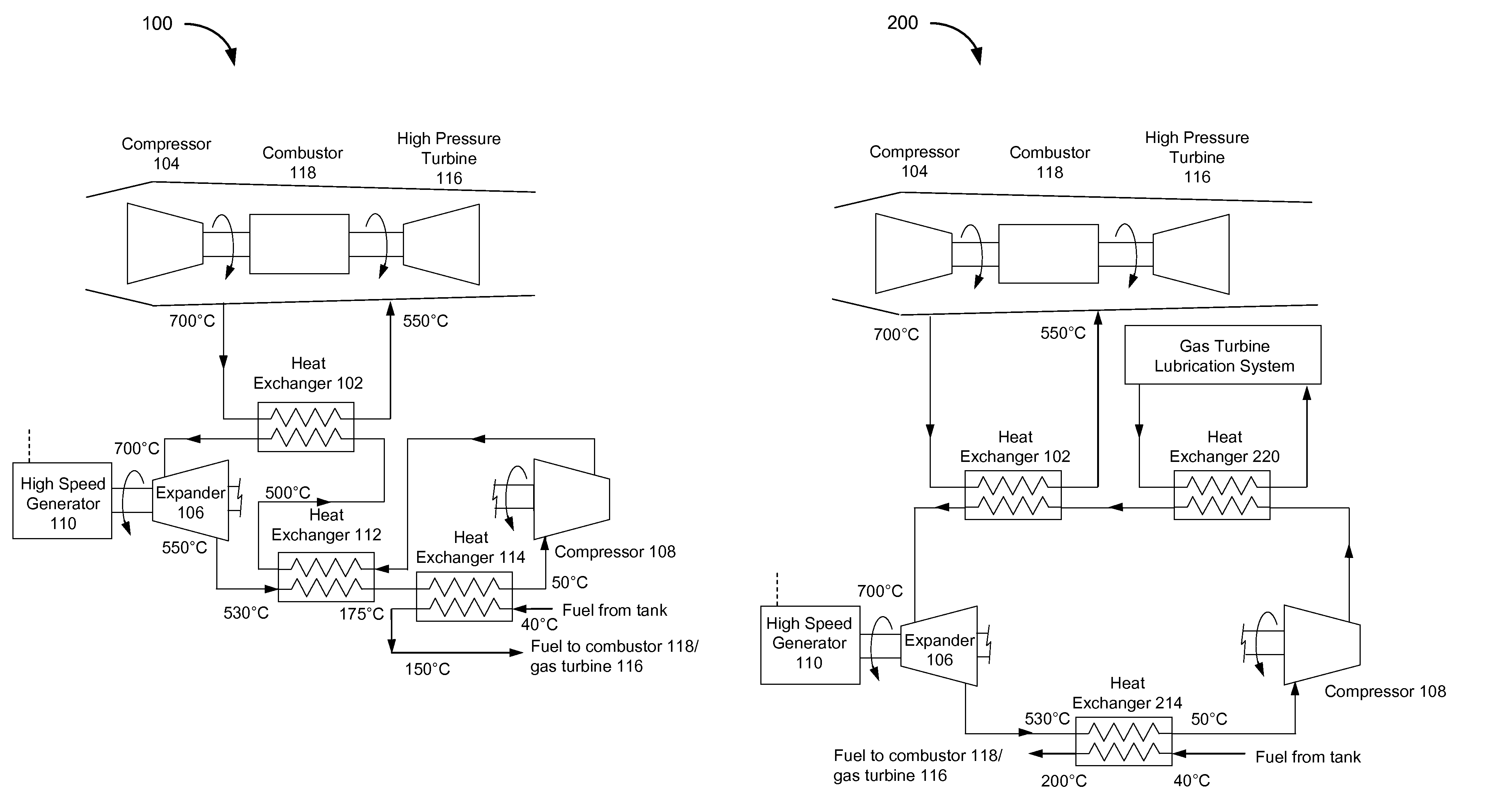
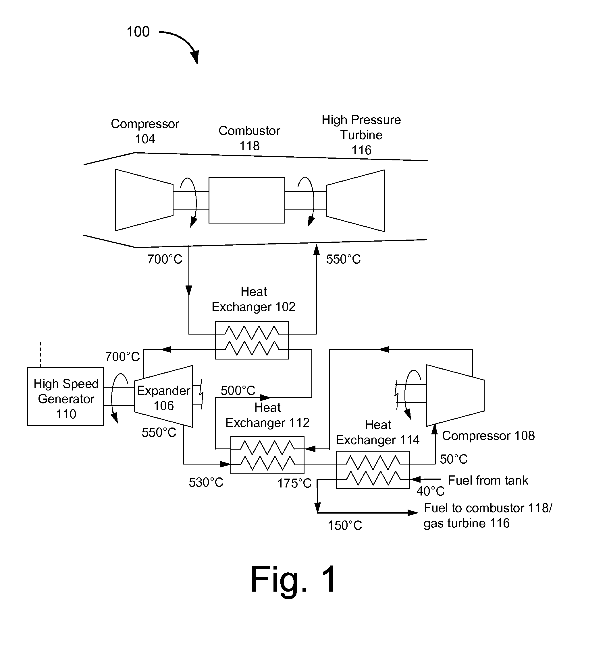
[0014]The present invention generally relates to a system that enables one to address various thermal management issues in advanced gas turbine engines. In one embodiment, the present invention relates to a method to extract heat from an air stream, utilize a significant fraction for on-board power generation, and reject a small quantity of heat to the fuel stream safely at, for example, a lower temperature. In another embodiment, the present invention relates to a method to extract heat from an air stream, utilize a significant fraction for on-board power generation, and reject a small quantity of heat to the fuel stream safely at, for example, a lower temperature with no potential air / fuel contact is disclosed.

[0015]A method to extract heat from the air stream, utilizing a significant fraction for on-board power generation, and reject a smaller quantity of heat to the fuel stream safely (at lower temperature, with no potential air / fuel contact) is disclosed herein (see, e.g., FIG....


PUM


Abstract

The present invention generally relates to a system that enables one to address various thermal management issues in advanced gas turbine engines. In one embodiment, the present invention relates to a method to extract heat from an air stream, utilize a significant fraction for on-board power generation, and reject a small quantity of heat to the fuel stream safely at, for example, a lower temperature. In another embodiment, the present invention relates to a method to extract heat from an air stream, utilize a significant fraction for on-board power generation, and reject a small quantity of heat to the fuel stream safely at, for example, a lower temperature with no potential air / fuel contact is disclosed.

Description

FIELD OF THE INVENTION[0001]The present invention generally relates to a system that enables one to address various thermal management issues in advanced gas turbine engines. In one embodiment, the present invention relates to a method to extract heat from an air stream, utilize a significant fraction for on-board power generation, and reject a small quantity of heat to the fuel stream safely at, for example, a lower temperature. In another embodiment, the present invention relates to a method to extract heat from an air stream, utilize a significant fraction for on-board power generation, and reject a small quantity of heat to the fuel stream safely at, for example, a lower temperature with no potential air / fuel contact is disclosed.BACKGROUND OF THE INVENTION[0002]Thermal management of advanced gas turbine engines is one of the most difficult constraints on continued performance improvements. Improved thermodynamic efficiency drives the cycle designer to higher compressor pressure...

Claims


Application Information

Patent Timeline
Patent Type & Authority Patents(United States)
IPC IPC(8): F02C7/08F02C7/06F02C1/06F02C3/34F02C6/18F02C7/12F02C7/14F02C7/16F02C7/224F02K3/115
CPCF02K3/115F02C7/12F02C7/16F02C1/06F02C3/34F02C6/18F02C7/14F02C7/224Y02T50/671Y02T50/675Y02T50/60
Inventor HELD, TIMOTHY JAMES
Owner ECHOGEN POWER SYST LLC
Learn More