Fuel injection control device for internal combustion

a control device and fuel injection technology, applied in the direction of electrical control, process and machine control, instruments, etc., can solve the problems of affecting the operation of the fuel injection control devi

Inactive Publication Date: 2015-04-28
TOYOTA JIDOSHA KK
View PDF24 Cites 0 Cited by
  • Summary
  • Abstract
  • Description
  • Claims
  • Application Information

AI Technical Summary

Benefits of technology

[0009]A fuel injection control device as one form of the present invention actuates two injectors together in a case where a requested fuel injection quantity is equal to or greater than a reference value. The reference value is set to a value that is equal to or greater than a sum of lower limit injection quantities of the respective injectors. At such time, the present fuel injection control device makes a proportion of fuel that is injected from an injector disposed at a downstream position in an intake pipe larger than a proportion of fuel that is injected from an injector disposed at an upstream position in the intake pipe. By deciding the injection proportion of each injector in this manner, a cooling effect produced by fuel at the downstream-side injector that is at a thermally severe position can be increased. In addition, by also injecting fuel from the upstream-side injector, the upstream-side injector itself is cooled by fuel, and at the same time, the downstream-side injector can be further cooled by latent heat of vaporization when the injected fuel of the upstream-side injector vaporizes. Note that when the requested fuel injection quantity is less than the reference value, it is preferable to actuate only the downstream-side injector that is disposed under a thermally severe condition to thereby promote cooling by fuel.
[0010]According to a more preferable form of the present invention, when actuating the two injectors together, the present fuel injection control device increases a proportion of fuel that is injected by the injector on the upstream side as an intake air quantity increases. That is, as the intake air quantity increases, the ratio between the proportion of fuel injected by the upstream-side injector and the proportion of fuel injected by the downstream-side injector approaches a 1:1 ratio. As the intake air quantity increases, an effect by the air carrying away heat increases. In addition, a cooling effect that is produced by fuel also increases as the fuel injection quantity increases. Therefore, as the intake air quantity increases, the proportion of fuel that is injected by the downstream-side injector can be reduced while still suppressing the adherence of deposits. Further, in the case of fuel injection by the upstream-side injector, since a certain time period exists from when the fuel is injected until the fuel enters the cylinder, it is easier for atomization of fuel to proceed in comparison to fuel injection by the downstream-side injector. Hence, by increasing the proportion of fuel that is injected by the upstream-side injector, atomization of fuel can be promoted to thereby improve the homogeneity of the air-fuel mixture.
[0011]According to another preferable form of the present invention, when actuating the two injectors together, the present fuel injection control device causes the two injectors to perform fuel injection by synchronous injection. According to the synchronous injection, air that is taken into the cylinder is cooled by latent heat of vaporization when fuel vaporizes, and thus the in-cylinder temperature can be lowered. If the in-cylinder temperature falls, not only can knocking be reduced, but an improvement in fuel consumption and an improvement in transient torque characteristics can also be achieved as the result of an improvement in the air charging efficiency. Further, since fuel injected from the upstream-side injector rides on the intake air flow and vaporizes in the vicinity of the downstream-side injector, it is possible for a significant cooling effect on the downstream-side injector to be obtained by means of latent heat of vaporization.
[0012]When performing fuel injection by synchronous injection at two injectors in this manner, it is preferable to make the proportion of fuel injected by the downstream-side injector smaller in comparison to a case of injecting fuel of identical quantities by asynchronous injection. This is because, according to synchronous injection, the fuel quantity that is injected from the downstream-side injector can be reduced by an amount that corresponds to the increase in the cooling effect on the downstream-side injector that is obtained by means of latent heat of vaporization. By increasing the proportion of fuel injected by the upstream-side injector by the aforementioned amount, atomization of the fuel can be promoted further and the homogeneity of the air-fuel mixture can be further improved.
[0014]Note that a fuel injection quantity that is injected by each injector can be controlled by means of the fuel injection time periods as long as there is no significant difference in the specifications of the two injectors. However, if the flow rates of the two injectors are made different to each other, specifically, if the flow rate of the downstream-side injector is made greater than the flow rate of the upstream-side injector, it is possible to make the fuel injection periods at the two injectors approximately identical to unify the control. Further, a fuel pressure of the downstream-side injector may be made larger than a fuel pressure of the upstream-side injector. Thus, a fuel injection quantity per unit time that is injected by the downstream-side injector can be increased, and atomization of fuel that is injected by the downstream-side injector is also enabled.

Problems solved by technology

However, even in the aforementioned internal combustion engine, if a requested injection quantity is less than a sum of the lower limit injection quantities of the respective injectors, it is necessarily only possible to actuate either one of the injectors.
However, adherence of deposits to an injector can also occur in a situation in which fuel is being injected.
In particular, since an injector on a downstream side is located in a thermally severe environment in comparison to an injector on the upstream side, adherence of deposits thereto is liable to occur.
However, when the problem regarding adherence of deposits to the injector on the downstream side is taken into account, it can not be said that simply setting the injection proportions to a ratio of 1:1 is necessarily the most suitable example.

Method used


Image

  • Fuel injection control device for internal combustion
  • Fuel injection control device for internal combustion
  • Fuel injection control device for internal combustion

Examples


embodiment 1

[0024]Embodiment 1 of the present invention will now be described with reference to the drawings.

[0025]An internal combustion engine to which a fuel injection control device of the present embodiment is applied is an internal combustion engine for an automobile. More specifically, the internal combustion engine is a premixed combustion-type four-stroke, one-cycle reciprocating engine. The fuel injection control device of the present embodiment is implemented as one function of an ECU that controls the overall operations of the internal combustion engine.

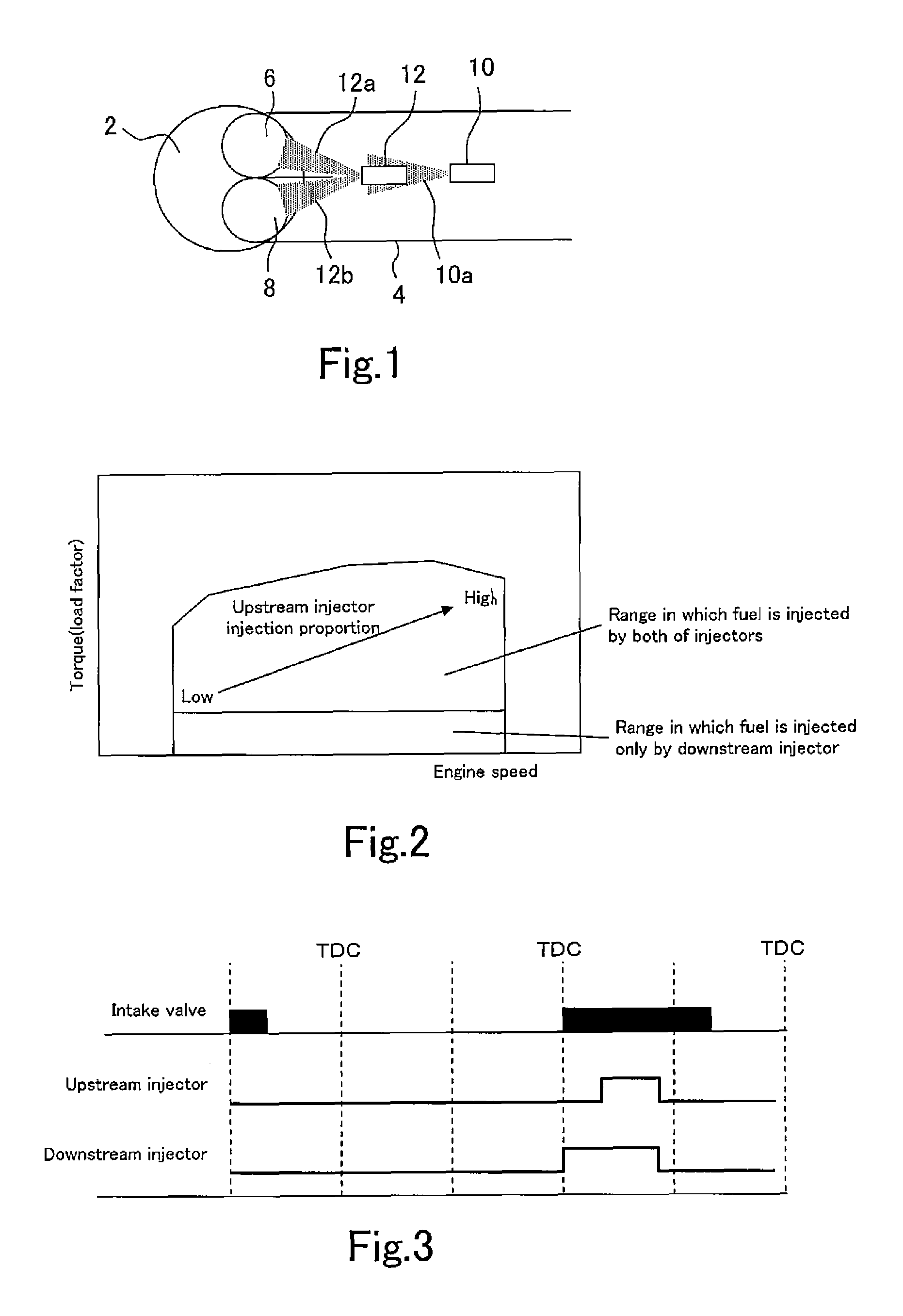
[0026]FIG. 1 is a view that illustrates a configuration in an area around an intake port of the internal combustion engine to which the present fuel injection control device is applied. In the internal combustion engine to which the present fuel injection control device is applied, a distal end of an intake pipe 4 branches into two intake ports 6 and 8, and the respective intake ports 6 and 8 are connected to a combustion chamber 2. ...

embodiment 2

[0033]Embodiment 2 of the present invention will now be described with reference to the drawings.

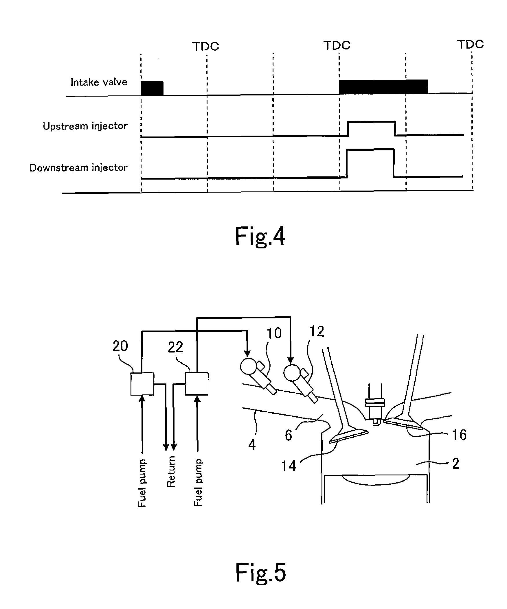
[0034]Similarly to Embodiment 1, a fuel injection control device according to the present embodiment is applied to an internal combustion engine that is configured as shown in FIG. 1. However, according to the present embodiment, the flow rate of the second injector 12 on the downstream side is made greater than the flow rate of the first injector 10 on the upstream side. A timing chart that illustrates injection periods of the respective injectors 10 and 12 when both of the injectors 10 and 12 are actuated in this case is shown in FIG. 4. As shown in the timing chart, the fuel injection period required by the second injector 12 can be shortened by increasing the flow rate of the second injector 12. Consequently, the fuel injection periods at the two injectors 10 and 12 can be made approximately the same, and it is possible to unify the control between the two injectors 10 and 12.

[0035]N...

embodiment 3

[0036]Embodiment 3 of the present invention will now be described with reference to the drawings.

[0037]Similarly to Embodiment 1, a fuel injection control device according to the present embodiment is applied to an internal combustion engine that is configured as shown in FIG. 1. However, a feature of the internal combustion engine to which the present fuel injection control device is applied is the configuration of a fuel supply system thereof. In the present embodiment, the fuel supply system of the internal combustion engine is configured as shown in FIG. 5. FIG. 5 illustrates a state in which an intake valve 14 is open and an exhaust valve 16 is closed, that is, the state of the internal combustion engine at the time of an intake stroke. In FIG. 5, components or sites that are the same as components or sites shown in FIG. 1 are denoted by the same reference numerals as in FIG. 1.

[0038]As shown in FIG. 5, the internal combustion engine to which the present fuel injection control ...


PUM


Abstract

The purpose of the present invention is to suppress, in an internal combustion engine in which two injectors are disposed in a line upstream and downstream in an intake pipe, adhesion of deposits to the downstream-side injector. In order to suppress such adhesion, a fuel injection control device according to one embodiment of the present invention operates both injectors together when a required fuel injection amount is equal to or greater than a reference value. The reference value is set to a value equal to or greater than the sum of lower limit injection amounts of the injectors. In such case, the fuel injection control device adjusts the proportion of fuel injected from the injector disposed downstream in the intake pipe to be greater than the proportion of fuel injected from the injector disposed upstream in the intake pipe.

Description

CROSS REFERENCE TO RELATED APPLICATIONS[0001]This application is a National Stage of International Application No. PCT / JP2011 / 058044 filed Mar. 30, 2011, the contents of all of which are incorporated herein by reference in their entirety.TECHNICAL FIELD[0002]The present invention relates to a fuel injection control device for an internal combustion engine, and more particularly to a fuel injection control device for an internal combustion engine that includes a first injector that is disposed at an upstream position in an intake pipe and a second injector that is disposed at a downstream position in the intake pipe.BACKGROUND ART[0003]An internal combustion engine in which two injectors are disposed in an aligned relationship at an upstream position and a downstream position in an intake pipe and which is configured to actuate both injectors to perform fuel injection is known. However, even in the aforementioned internal combustion engine, if a requested injection quantity is less t...

Claims


Application Information

Patent Timeline
Patent Type & Authority Patents(United States)
IPC IPC(8): F02M43/00F02D19/08F02B5/00F02D41/00F02D41/18F02D41/30F02D41/32F02M69/04
CPCF02M69/04F02D41/3094F02D19/08F02D41/32F02M69/042F02D41/0065F02D41/18
Inventor KANEKO, NAOYA
Owner TOYOTA JIDOSHA KK
Why Eureka
Try Eureka