

Method of forming electrodes comprising sulfur and porous material comprising carbon
a technology of porous material and carbon, which is applied in the field of electrodes and electrochemical cells, can solve the problems of limiting the amount of electroactive material loading achieved in the electrode, affecting the resulting electrode structure, and unable to achieve high electroactive material loading, etc., and achieves the effect of increasing the surface area
- Summary
- Abstract
- Description
- Claims
- Application Information
AI Technical Summary
Benefits of technology
Problems solved by technology
Method used
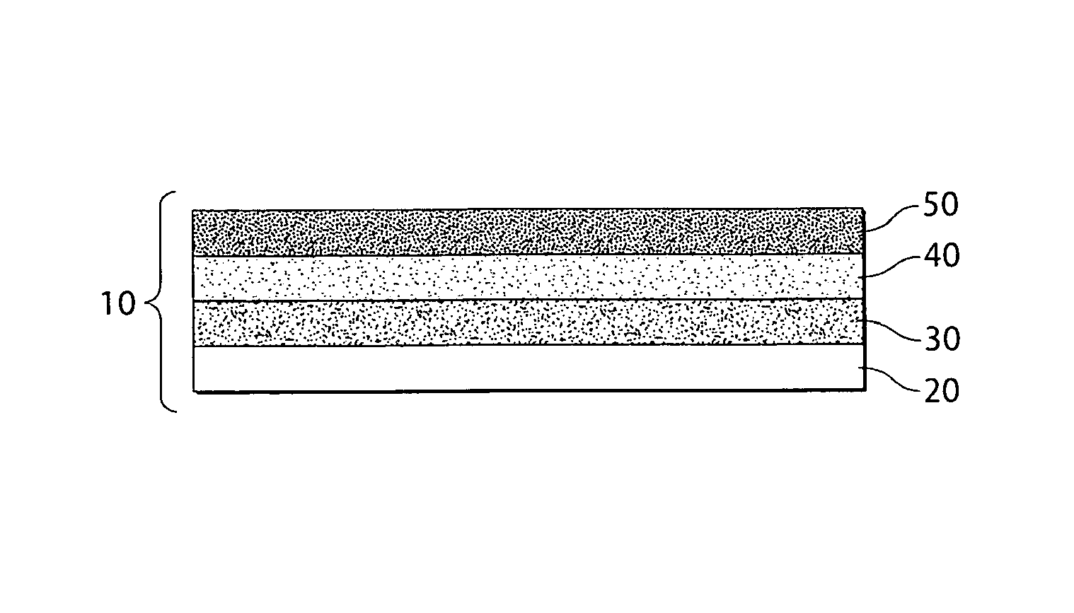
Image

Examples
example 1
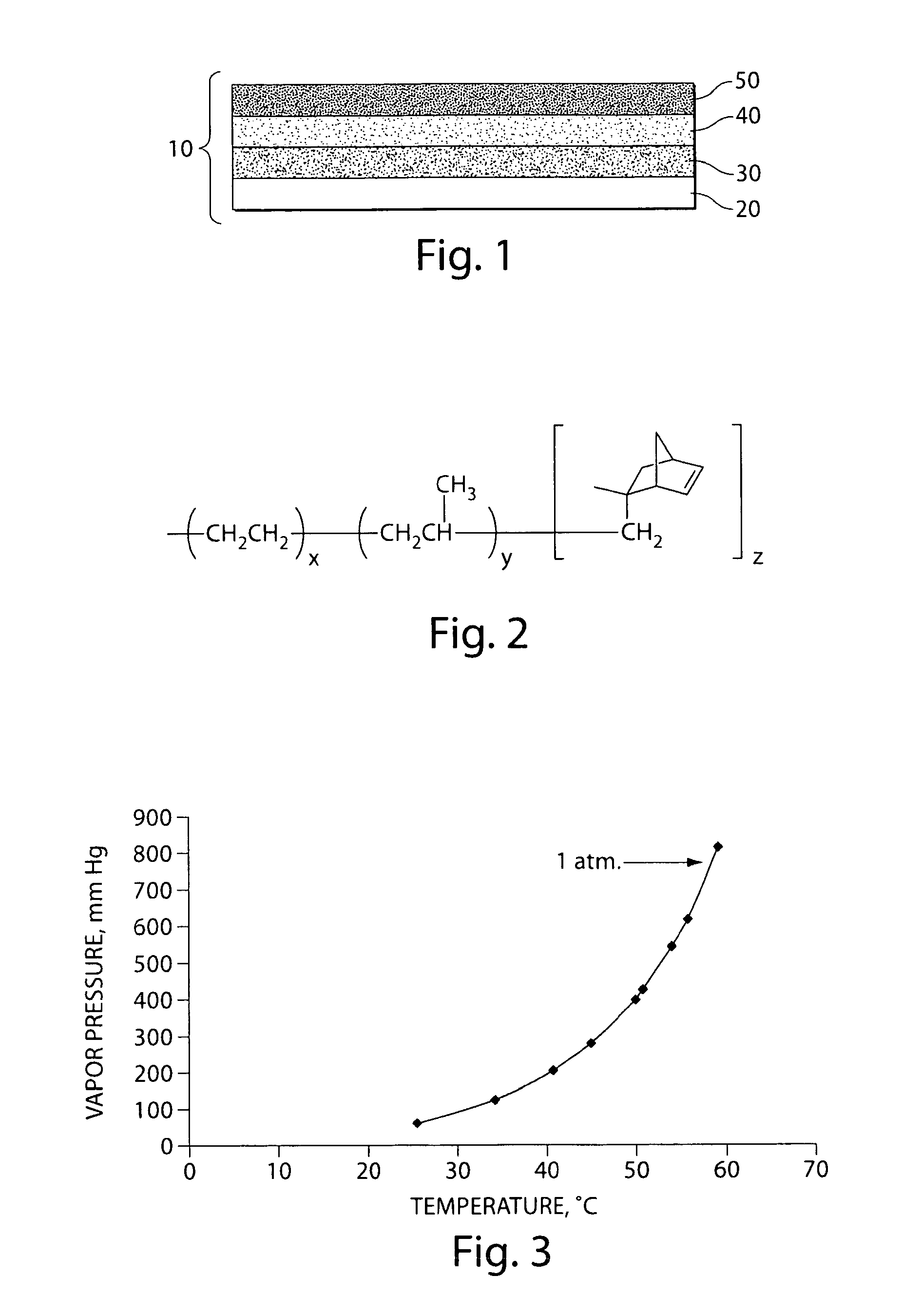
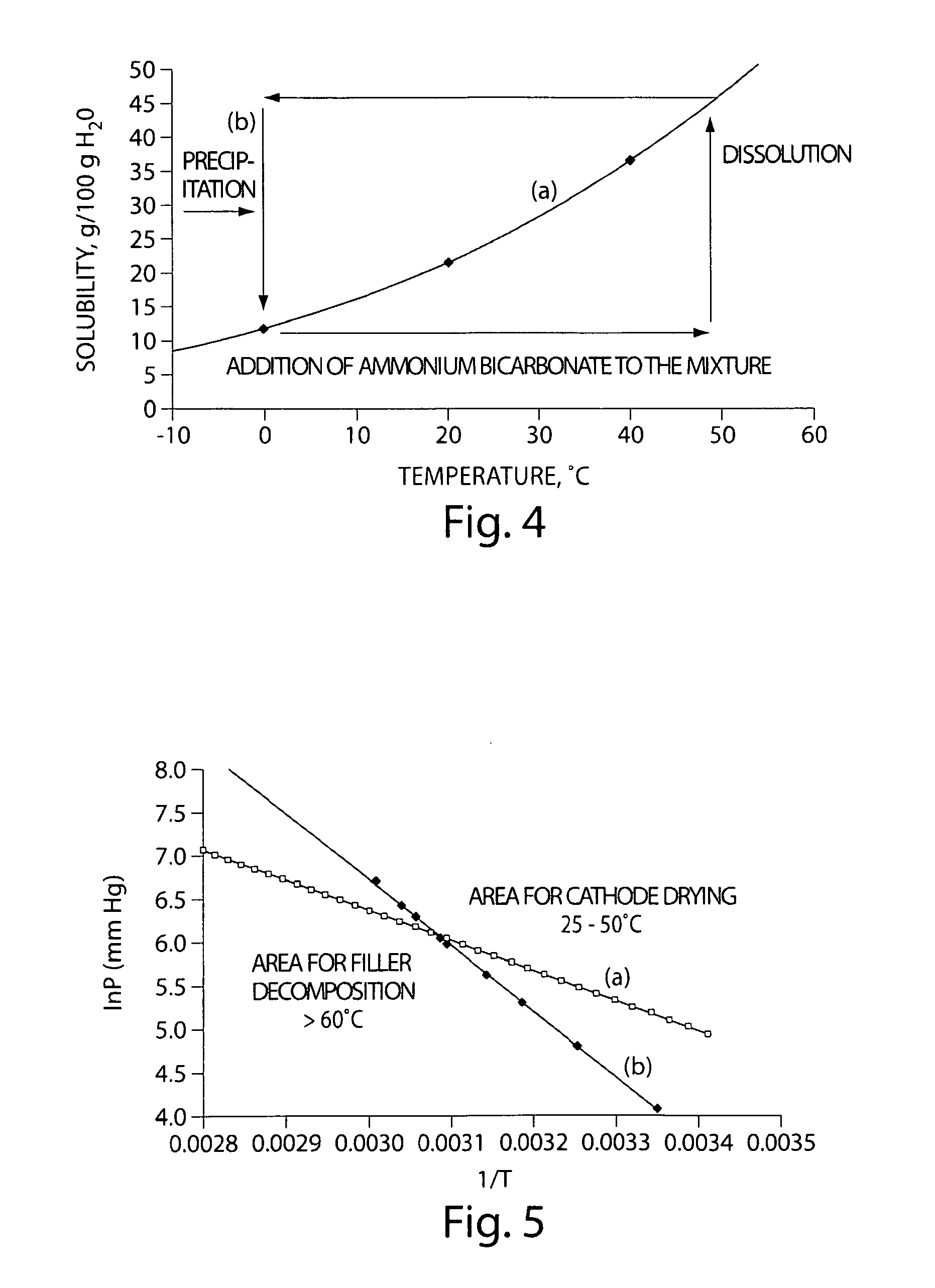
[0093]The following examples described the formation of a filler material within the pores of a porous carbon material, according to one embodiment of the invention.
[0094]A filler material was formed on porous carbon material by thermal cycling to repeatedly dissolve and precipitate a filler material within the pores of the porous carbon material. In this example, ammonium carbonate or ammonium bicarbonate was used as the filler material, since each exhibits a positive temperature solubility gradient in water, i.e., the solubility of the ammonium carbonate or ammonium bicarbonate in water increases with increasing temperature and decreases with decreasing temperature. FIG. 4 shows a graph of (a) the solubility of ammonium bicarbonate in water as a function of temperature, and (b) the thermal cycling diagram of ammonium bicarbonate in water.
[0095]According to the thermal cycling diagram in FIG. 4B, an aqueous solution of ammonium carbonate or ammonium bicarbonate was contacted with t...
example 2
[0096]In the following example, an electrochemical cell was prepared using a filler material and a soluble binder material, as described herein, and its sulfur specific capacity was evaluated.
[0097]A composite comprising XE2 carbon (11.1 wt %) and ammonium bicarbonate (88.9 wt %) was prepared by adding XE2 to a saturated solution of ammonium bicarbonate at 50° C. or greater. The mixture was then cooled to 0° C. and NH4HCO3 was allowed to precipitate in the carbon pores. The precipitated NH4HCO3 was filtered to provide the XE2 composite, which was then washed with ethanol. The composite (21.37 g) was then mixed with 33.3 g of a solution of 3 wt % EPDMN binder in hexane and 6.63 g of sulfur powder. An additional 35.3 g of hexane was added to the slurry mixture, which was then milled for 40 minutes with stainless steel balls in a vial.
[0098]To coat the cathode, the milled slurry mixture was hand drawn on a carbon-coated 12 micron Al substrate (AL Rexam primer), and the coated cathode w...
example 3
[0101]In the following example, an electrochemical cell was prepared using a filler material and a soluble binder material, as described herein, and its sulfur specific capacity was evaluated.
[0102]An XE2-ammonium carbonate (NH4)2CO3 composite having an XE2 content of 15.7 wt % and an ammonium bicarbonate content of 84.3 wt % was prepared according to the method described in Example 2. The composite was then mixed with 33.3 g of a solution of 3 wt % EPDMN binder in hexane and 6.63 g of sulfur powder. The XE2-(NH4)2CO3 composite was then coated as described in Example 2, using a milled hexane slurry mixture containing 9.97% sulfur, 22.06% XE2-(NH4)2CO3 composite, and 1.5% EPMN soluble binder, by weight. The coated cathode was dried at +70° C. in the oven for 1 hour to remove the solvent and filler material. The resulting composite contained sulfur (66.3 wt %), XE2 (23.7 wt %), EPDMN (10 wt %). The cathode had a good adhesion and cohesion. The sulfur coated loading was 4.3 mg / cm2.
[010...
PUM
| Property | Measurement | Unit |
|---|---|---|
| porosity | aaaaa | aaaaa |
| porosity | aaaaa | aaaaa |
| porosity | aaaaa | aaaaa |
Abstract
Description
Claims
Application Information