Patch and patch preparation

a patch and patch technology, applied in the field of patch and patch preparation, can solve the problems of patch being easily detached from the skin, patch being markedly weakened, high stretchability, etc., and achieves the effects of easy adhesion to the skin, low stretchability, and patch stretchability

Active Publication Date: 2015-05-26
NITTO DENKO CORP
View PDF33 Cites 0 Cited by
  • Summary
  • Abstract
  • Description
  • Claims
  • Application Information

AI Technical Summary

Benefits of technology

[0025]On the other hand, when the curved sections 5 are approximated by a circular arc, and the radius R 11 (mm) of the circular arc is too small, since the curved section is entangled with the fiber of the clothes, the stress from the clothes is concentrated on the curved section, and the patch tends to start detaching early from the curved section 5. From such aspect, when the curved sections 5 are approximated by a circular arc, the radius R (mm) of the circular arc needs to be 0.5 mm or above. To exhibit sufficient effect of the invention, R (mm) is preferably not less than 0.75 mm, more preferably not less than 1.00 mm. The radius of the circular arc of all the curved sections of the outer shape of the patch is preferably not less than 0.5 mm. While R is not particularly limited as long as it is not less than 0.5 mm, since P tends to increase as R becomes higher, it is preferably smaller than 40, more preferably smaller than 20, most preferably not more than 19.5.
[0026]In the present invention, the patch needs to be low stretchable. When the patch is low stretchable, the patch acquires rigidity, and easily adhered to the skin. Typically, therefore, the stretchability of the patch can be achieved by the selection of a support.
[0027]In the present invention, the “low stretchability” means a 5% modulus of not less than 0.5 N, preferably not less than 1.0 N. In the present specification, 5% modulus means the force [N] necessary for expanding a test piece by 5% while affording a width of 10 mm and at least a chuck interval of 10 mm. To avoid doubt, the test piece does not have a release liner. The influence of the size of the test piece on the 5% modulus is neglectably small as long as the size is within the size range of conventional patches. When a sufficiently large test piece is obtained, a patch test piece of width 25 mm, length 100 mm is cut out and the 5% modulus thereof is measured according to the test method described in JIS Z 0237-2000.
[0028]The stretchability of the patch can be adjusted by a method known to those of ordinary skill in the art. Since the support can be an important factor to define the stretchability of the patch since the stretchability of a flexible adhesive layer can be almost ignored.
[0029]While such a support is not particularly limited, it desirably has a certain level of rigidity to enable easy adhesion of a patch to the skin.
[0030]Examples of the support include single films such as resin films (e.g., polyester, nylon, Saran (registered trade mark), polyethylene, polypropylene, polyvinyl chloride, ethylene-ethyl acrylate copolymer, polytetrafluoroethylene, Surlyn (registered trade mark) and the like), metal foil and the like; laminate films thereof, and the like. The thickness of the support is generally 10-500 μm, preferably 10-300 μm.

Problems solved by technology

However, the patch may be undesirably detached and markedly fall off from the skin due to various factors during adhesion.
For even such patches, however, when the patch is adhered for a long time to the skin covered with clothes, the patch may be detached due to the friction with the clothes.
In addition, the patches of the above-mentioned references have high stretchability, and a detach operation necessary when detachment is desired is relatively troublesome.
The references do not teach any solving means for providing a patch with low stretchability wherein the detachment from the skin is sufficiently suppressed even when it is adhered for a long time to the skin covered with clothes.

Method used


Image

  • Patch and patch preparation
  • Patch and patch preparation
  • Patch and patch preparation

Examples


example 1

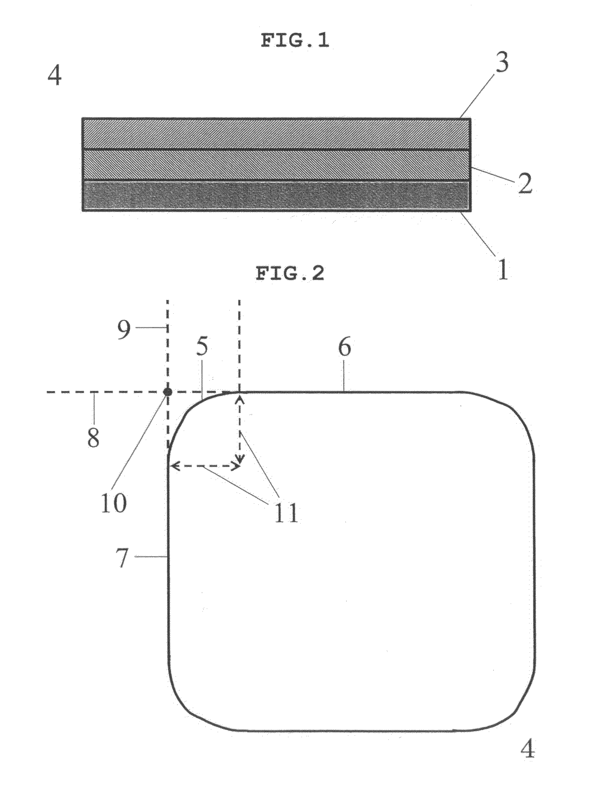
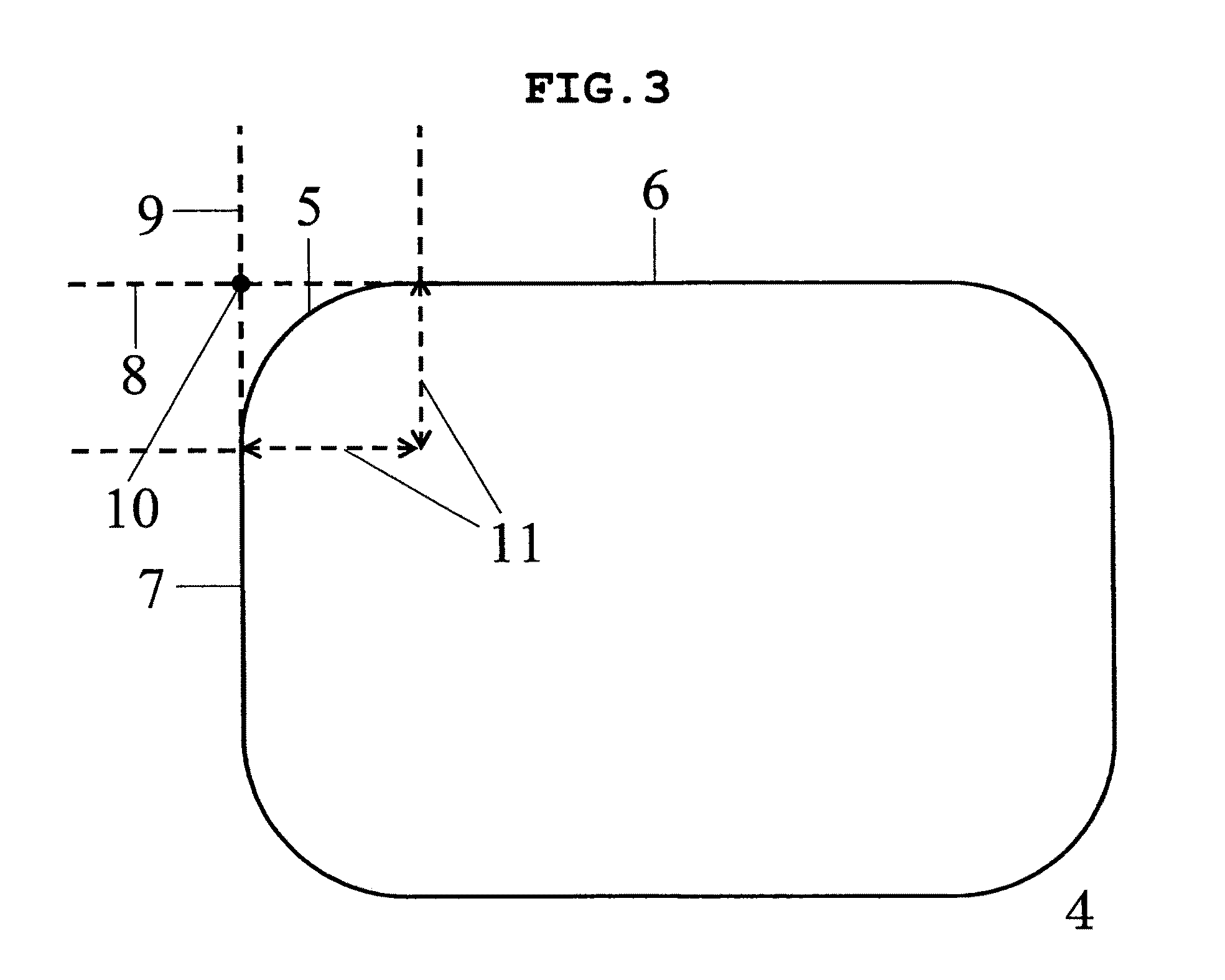
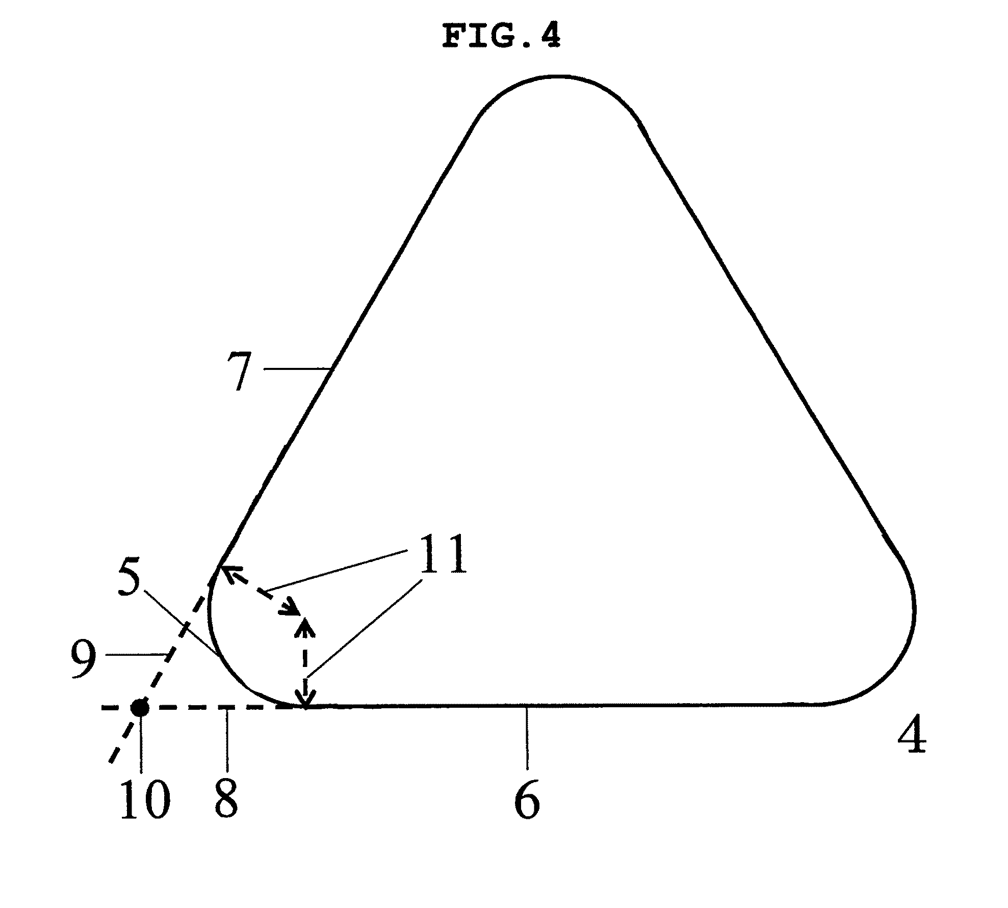
[0058]An acrylic adhesive solution in an amount to set an adhesive solid content to 44 parts and isopropyl myristate (54 parts) were stirred in a container to give a uniform mixture. To this mixture was added ethylacetoacetate aluminum diisopropylate in the proportion of 0.4 part per 100 parts of the solid content of the acrylic adhesive solution, the viscosity was adjusted with ethyl acetate, the liquid was laminated on a PET film (75 μm-thick) as a release liner such that the thickness of the adhesive layer after drying was 200 μm, adhered to a non-woven fabric side of a support ((total) thickness 54 μm) consisting of 2 μm-thick polyethylene terephthalate (hereinafter to be indicated as “PET”) film / PET non-woven fabric (fabric weight 12 g / m2), and aged (crosslinking treatment of adhesive layer) at 70° C. for 48 hr. The laminated sheet after aging was cut such that, when adjacent two straight-line sections of the curved sections of the planar outer shape are extended and the point ...

example 2

[0059]A patch was obtained in the same manner as in Example 1 except that the laminated sheet after aging was cut such that the corner was a circular arc with radius of 1.0 mm.

example 3

[0060]A patch was obtained in the same manner as in Example 1 except that the laminated sheet after aging was cut into length and width 63.5 mm (corner was a circular arc with radius 5 mm).


PUM

PropertyMeasurementUnit
radiusaaaaaaaaaa
thickaaaaaaaaaa
radiusaaaaaaaaaa

Abstract

The present invention provides to a patch and a patch preparation having low stretchability, which can be continuously adhered to the skin for a long time without undesirable detachment and marked falling off from the skin due to various factors during adhesion, and specifically provides a low stretchable patch and a patch preparation containing a support and an adhesive layer formed on one surface of the support, wherein a ratio P of the total length W (mm) of curved sections of a planar outer shape of the patch to the total length S (mm) of straight-line sections of the planar outer shape of the patch (W / S) is not more than 1.22, and, when the curved sections are approximated by a circular arc, the radius R (mm) of the circular arc is not less than 0.5 mm.

Description

TECHNICAL FIELD OF THE INVENTION[0001]The present invention relates to a patch and a patch preparation having a support and an adhesive layer. More particularly, the present invention relates to a patch and a patch preparation having low stretchability, which can be continuously adhered to the skin for a long time without undesirable detachment and marked falling off from the skin due to various factors during adhesion.BACKGROUND OF THE INVENTION[0002]Patch preparations having a rectangular outer shape are conventionally known. However, the patch may be undesirably detached and markedly fall off from the skin due to various factors during adhesion. As references dealing with, the problems of undesirable detachment, for example, the following references can be mentioned.[0003]JP-A-2000-109427 (patent document 1) discloses a patch having a water-containing adhesive layer formed on one surface of a support and a support having an atypical outer shape, and teaches that such patch shows ...

Claims


Application Information

Patent Timeline
Patent Type & Authority Patents(United States)
IPC IPC(8): A61L15/16A61K9/70A61F13/00
CPCA61K9/703A61K9/7061A61F2013/00651A61P43/00A61F13/00029A61F13/02A61F13/0269A61F2013/00561A61L15/58
Inventor TERASHI, SACHIKOHANATANI, AKINORIAKEMI, HITOSHIIWAO, YOSHIHIRO
Owner NITTO DENKO CORP
Why Eureka
Try Eureka