
Separator device, deposition device and system for handling of somatic plant embryos

a technology of somatic plant embryos and separation devices, which is applied in the field of separation devices, deposition devices and systems for handling somatic plant embryos, can solve the problems of increased manual labor needed to collect embryos, decreased conversion rate, cost and risk of contamination, etc., and achieves cost-effective effects

Active Publication Date: 2015-05-26
GEORGIA TECH RES CORP
View PDF19 Cites 4 Cited by
  • Summary
  • Abstract
  • Description
  • Claims
  • Application Information

AI Technical Summary

Benefits of technology

Enables rapid, efficient, and cost-effective separation and deposition of somatic embryos, reducing manual handling and equipment complexity, thereby improving the scalability and accuracy of plant production from somatic embryogenesis.

Problems solved by technology

The manual labour needed to collect embryos increase with the decrease in conversion rate, and thereby the cost and risk of contamination and other inaccuracies.
Low conversion rate from proliferation to maturation is a major bottleneck for commercial large scale applications of somatic embryogenesis procedures.
The different treatments during germination into a plant requires repeated manual handling of individual germinants and plants adding a considerable cost to the overall procedure.
The prior art procedure for producing plants from somatic embryos requires manual handling at several steps making the procedure time consuming, expensive and inaccurate.
This is time-consuming and ineffective.
However, this approach, analogous to automating the wing motion of a bird by robotic wings for flight, is too complex and impractical for several reasons, as elaborated below.
This makes the process more complex, as embryos have to first be separated from the immature embryogenic tissue in the cluster by breaking up the cluster.
Prior art does not teach how to breakup the embryogenic clusters in an automated manner.
The tasks of image recognition and analysis become more difficult and tedious if the image contains more objects than just the embryo.
Furthermore, the task of image processing will be more time consuming with adverse impact on the processing and the conversion rates.
The prior art methods to make plants from somatic embryos require intensive manual handling, and are therefore expensive for plant production.
Attempts to automate the steps used in the manual operation have failed due to the complex devices developed to automate the manual transfer and delivery of embryos by means of moving parts such as conveyer belts and elaborate robotic arms.
A conveyer belt that has to move and stop each time an embryo is detected creates an inherently inefficient process.
In general, the prior art teaches an approach requiring many moving parts including the conveyer belts and the robotic arm assemblies making the current state of the art to be impractical.

Method used


Image

  • Separator device, deposition device and system for handling of somatic plant embryos
  • Separator device, deposition device and system for handling of somatic plant embryos
  • Separator device, deposition device and system for handling of somatic plant embryos

Examples


example 1

Separation

[0375]Several clusters of embryogenic mass of Norway Spruce (cell line 06:28:05) with average hydraulic diameter of the cross-section taken from the mid-section of the cluster ranging from 5 mm to 30 mm were collected from a periodically and partially immersed bioreactor and fed into a disperser of the PCT / US09 / 39981. An in vitro culture container as disclosed in WO9625484 was used as the bioreactor

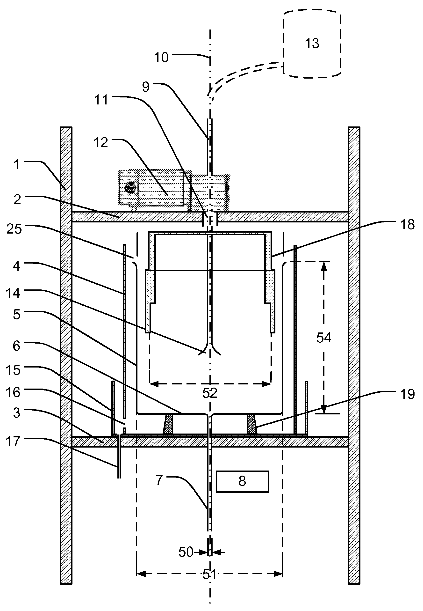
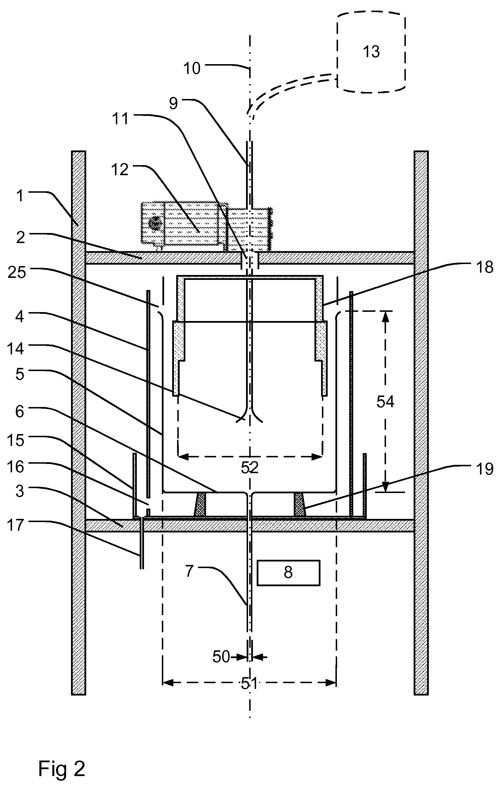
[0376]Upon passage through the disperser, the embryos fully dispersed in water, were fed through the feed conduit (9) and into the separator container (5). The rotation means (a disk) was rotating at the rate of 120 rpm for more than 20 minutes with the separator container (5) full of water prior to the injection of the clusters of embryogenic mass into the disperser. It is preferred to have the rotation means running for more than few minutes to eliminate the initial transients due to starting of the motor with a stationary liquid. A 500 mm glass flask was placed under the cond...

example 2

Deposition

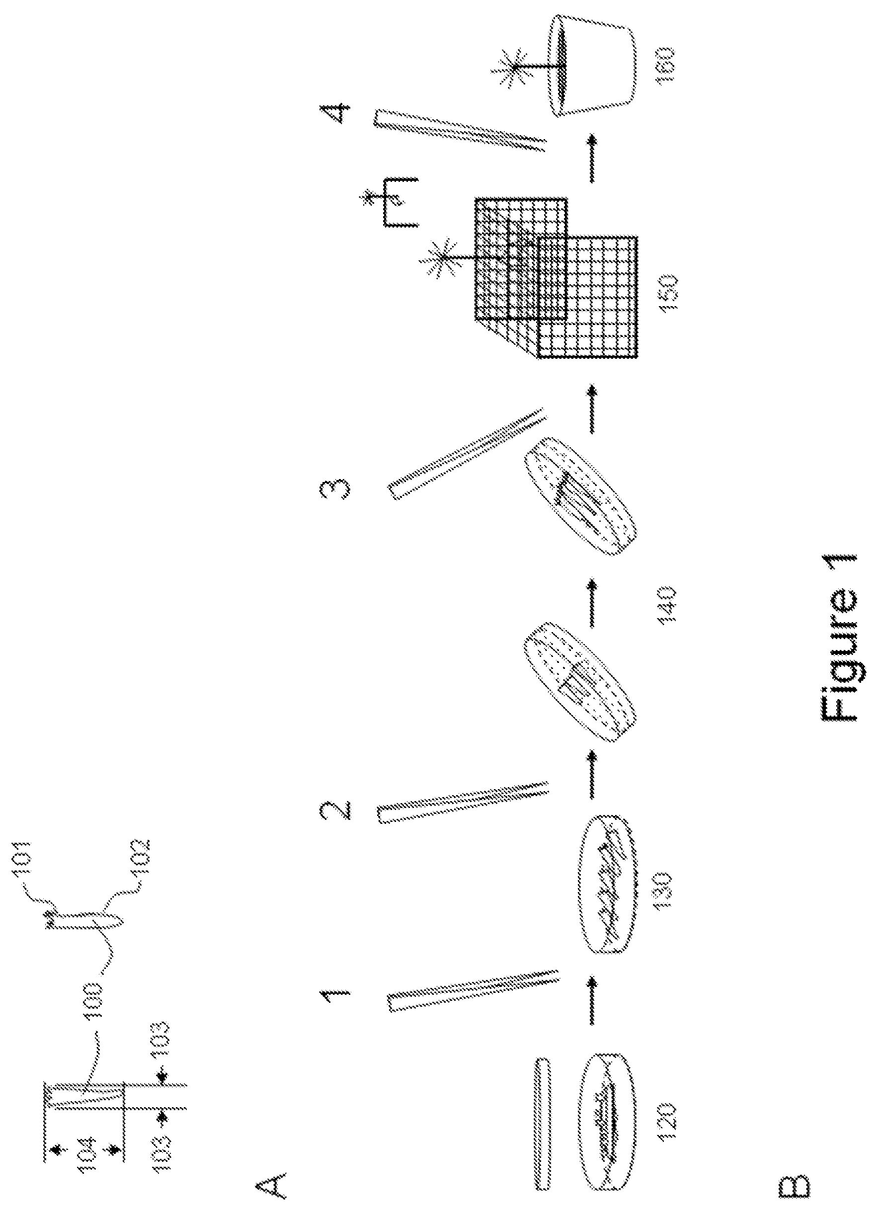
[0379]The deposition device of the invention, as shown in FIG. 11, comprises an x / y table with linear actuators (315) and a Singulareactor plate with 20 or more containers, each container for one individual embryo. The linear actuators (315) are attached to a control unit (38).

[0380]The embryo receiver is fixed on top of the x / y table in a precisely known position, such that the linear actuator software can accurately position the plate. The embryo receiver plate comprises a plurality of containers, preferably 50 or more, in a grid formation, preferable rectangular grid formation, with a specific centre-to-centre spacing, preferably about 25 mm. The container can have any shape appropriate for the application, preferably conical shape with a flat bottom, as shown in FIG. 11A. The wall and bottom of the container are perforated (305) to allow liquid medium to enter and drain freely into and out of the container. The embryo receiver plate contains a reservoir section (310) w...

example 3

Separation with Two Separation Units

[0381]In order to get pure and well separated mature embryos two separator (230) units were connected in series. The outlet tube (7) from the first separation unit was connected to the feed conduit (9) on the second separation unit. With this set up the amount of immature embryogenic tissue was reduced by 95% or more.


PUM

PropertyMeasurementUnit
diameteraaaaaaaaaa
diameteraaaaaaaaaa
diameteraaaaaaaaaa

Abstract

Methods and devices for separating fluid-suspended plant somatic embryos and embryogenic tissue based on differences in their fluid drag properties are disclosed. Deposition method and device for depositing plant somatic embryos into embryo receiver comprising growth substrate by means of a fluid jet is disclosed. An automated system for processing plant somatic embryos from the bioreactor to the growth substrate is also disclosed.

Description

CROSS REFERENCE TO RELATED APPLICATIONS[0001]This is a U.S. National Phase patent application of PCT / IB2010 / 054557, filed Oct. 8, 2010, which claims priority to the Swedish Patent Application No. 0950742-7, filed Oct. 9, 2009, and the U.S. Provisional Patent Application No. 61 / 250,015, filed Oct. 9, 2009, each of which is hereby incorporated by reference in the present disclosure in its entirety.BACKGROUND TO THE INVENTIONGeneral Introduction to Problem Area[0002]Somatic embryogenesis in plants is a process in which somatic embryos are formed from an initial explant being a cell in a plant tissue. The somatic embryos formed are genetically identical copies of the plant providing the initial explant. The process of somatic embryogenesis thereby offers a tool to obtain large numbers of genotypically identical plants for multiplication of selected genotypes of commercial interest, for conservation of endangered species or for generating genetically uniform plant material for research p...

Claims


Application Information

Patent Timeline
Patent Type & Authority Patents(United States)
IPC IPC(8): C12N5/00A01H4/00
CPCA01H4/001C12N5/00
Inventor AIDUN, CYRUS K.
Owner GEORGIA TECH RES CORP
Learn More