Twinaxial cable and twinaxial cable ribbon

a twin-axial cable and ribbon technology, applied in the field of twin-axial cables, can solve the problems of high cost, high cost, and high cost of connecting the conventional twin-axial cable ribbon , achieve the effects of low cost, high signal integrity and quality, and high speed

Active Publication Date: 2015-05-26
SAMTEC
View PDF21 Cites 50 Cited by
  • Summary
  • Abstract
  • Description
  • Claims
  • Application Information

AI Technical Summary

Benefits of technology

[0022]Preferred embodiments of the present invention provide a low cost, high speed twinaxial cable ribbon with high signal integrity and quality and an improved cable density that allows for a smaller footprint area compared to conventional twinaxial cable ribbons. Preferred embodiments of the present invention also ensure a consistent distance between two center conductors of a twinaxial cable.

Problems solved by technology

A problem with this arrangement is that the outer PVC layer of each of the twinaxial cables increases the pitch between adjacent twinaxial cables.
Other problems are that this method requires the use of expensive materials, such as Teflon®, and that it requires multiple extrusions steps to prepare each of the twinaxial cables.
As shown in FIG. 8, one problem with conventional twinaxial cable ribbons is that a connection between the conventional twinaxial cable ribbon 1000 and a circuit board 1200 requires a large footprint 1210 on the circuit board 1200, due to the spacings between each of the twinaxial cables and the spacings between the one or more drain wires and the twinaxial cables.
Accordingly, the spacings between the twinaxial cables and between the drain wires and the twinaxial cables result in a relatively low-density cable that requires a large footprint, which may increase the cost of a system that uses the conventional twinaxial cable ribbon.
Another problem with conventional twinaxial cables is a variation in the electrical properties among each of the layers of insulation, since each of the center conductors has a separate insulating dielectric layer.
Since separately formed insulators do not have identical electrical properties, performance is degraded as compared to, for example, a pair of center conductors that share a single insulating layer.
Accordingly, the performance of the twinaxial cable may be further degraded due to stresses on the twinaxial cables during this extra manufacturing process.
An additional problem with conventional twinaxial cables is a non-constant distance between the center conductors of a differential pair due to shifting of the separately formed insulators during twisting, bending, stretching, or similar stresses of which twinaxial cables are often subjected.
Furthermore, any shifting of the relative positions of each of the center conductors may cause variation in the electrical properties of the twinaxial cables.
A further problem with conventional twinaxial cable ribbons is creating the connections between the conductive shields and the center conductors of the twinaxial cables and a circuit board.
Hand soldering is time consuming and expensive.
A problem with conventional hot bar soldering is that it requires two hot bar solder steps: once to solder the conductive shields and once to solder the center conductors.
However, hot bar soldering a served or braided conductive shield requires the use of materials that can withstand the high temperatures applied during the heating step of the hot bar soldering process.
Lower cost dielectric materials, such as polypropylene, are unable to withstand the temperatures applied in hot bar soldering a served or braided conductive shield.

Method used


Image

  • Twinaxial cable and twinaxial cable ribbon
  • Twinaxial cable and twinaxial cable ribbon
  • Twinaxial cable and twinaxial cable ribbon

Examples


Embodiment Construction

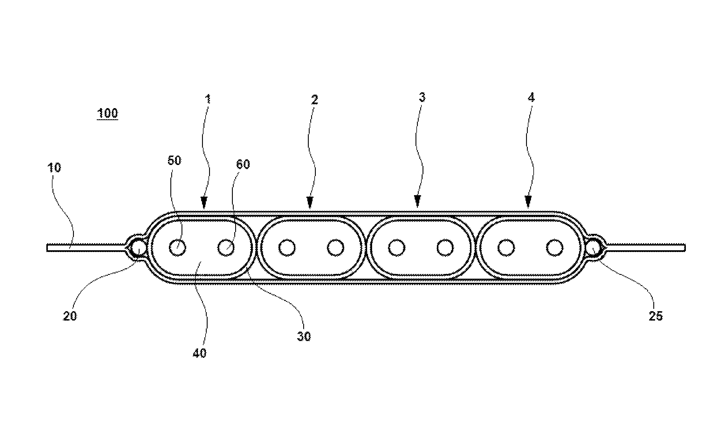
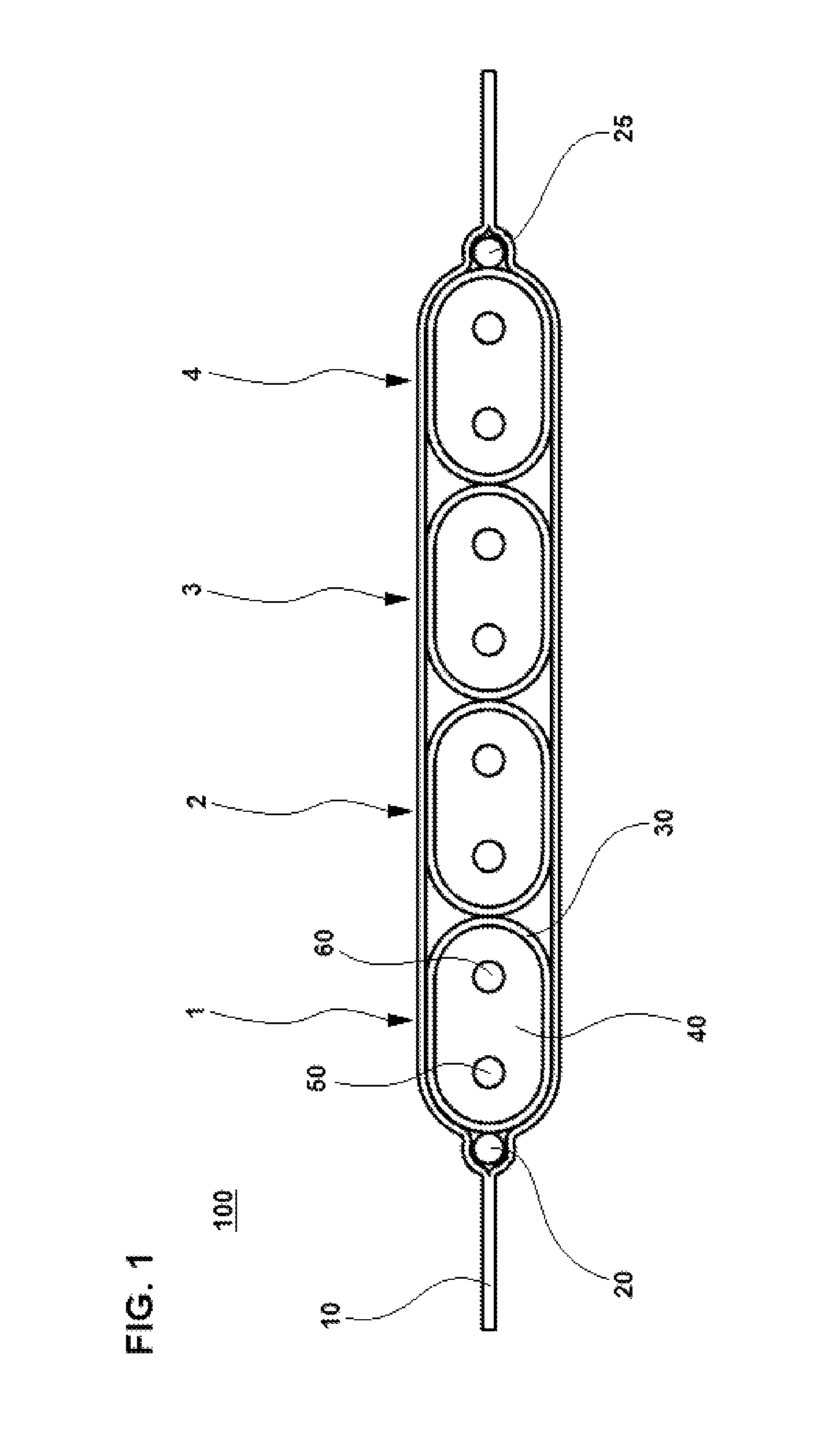
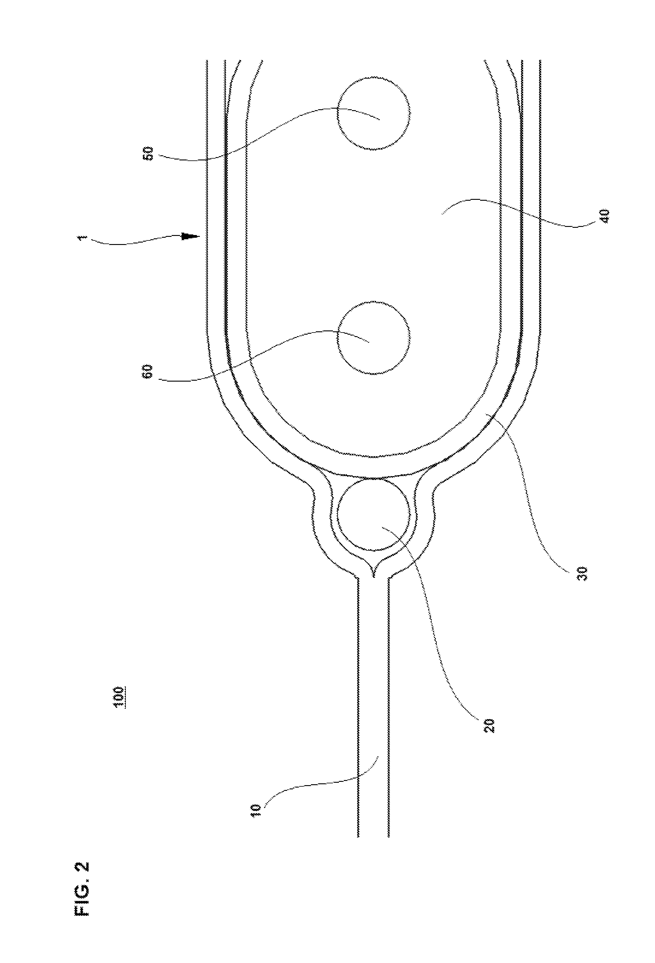
[0048]Preferred embodiments of the present invention will now be described with reference to FIGS. 1 to 6 and FIGS. 9A-12D. FIGS. 1 to 3 show a twinaxial cable ribbon 100 according to a preferred embodiment of the present invention. FIG. 4 shows a circuit board 200 according to a preferred embodiment of the present invention. FIGS. 5 and 6 show the twinaxial cable ribbon 100 shown in FIGS. 1 to 3 connected to the circuit board 200 shown in FIG. 4 according to a preferred embodiment of the present invention. FIGS. 9A-12D show the twinaxial ribbon 100 with various connectors according to several preferred embodiments of the present invention.

[0049]FIG. 1 shows a cross-sectional view of the twinaxial cable ribbon 100 according to a preferred embodiment of the present invention. The twinaxial cable ribbon 100 includes an outer layer 10, at least one drain wire 20, and at least one twinaxial cable 1. Twinaxial cable 1 includes a conductive shield 30, an insulator 40, a first conductor 50...


PUM

PropertyMeasurementUnit
center-to-center distanceaaaaaaaaaa
distanceaaaaaaaaaa
distancesaaaaaaaaaa

Abstract

A cable ribbon includes a first and second twinaxial cables and an outer layer surrounding the first and second twinaxial cables. The first twinaxial cable includes two first wires that are parallel or substantially parallel to each other along a longitudinal axis of the twinaxial cable ribbon, a first insulator surrounding each of the two first wires along the longitudinal axis, and a first conductive shield surrounding the first insulator along the longitudinal axis. The second twinaxial cable includes two second wires that are parallel or substantially parallel to each other along the longitudinal axis, a second insulator surrounding each of the two second wires along the longitudinal axis, and a second conductive shield surrounding the second insulator along the longitudinal axis. The first and second conductive shields are in direct contact with each other.

Description

BACKGROUND OF THE INVENTION[0001]1. Field of the Invention[0002]The present invention relates to twinaxial cables, and more specifically, the present invention relates to twinaxial cable ribbon.[0003]2. Description of the Related Art[0004]Coaxial cables include a center conductor surrounded by an insulation layer and a conductive shield covering the insulation layer. Typically, a protective layer covers the conductive shield.[0005]Twinaxial cables are similar to coaxial cables, but contain two center conductors instead of one. The two center conductors of a twinaxial cable are each surrounded by an insulation layer. Typically, the insulation layers for each of the two center conductors of twinaxial cables are separately formed. A conductive shield covers the insulation layers.[0006]Twinaxial cables are often used to provide high-speed differential signaling in electrical devices. For example, in differential signaling, complementary signals may be sent on respective center conductor...

Claims


Application Information

Patent Timeline
Patent Type & Authority Patents(United States)
IPC IPC(8): H01B11/06H01B7/08H01B11/20H01R12/59H01R12/62H05K3/34
CPCH01B11/203H01R12/598H01R12/62H05K3/3421H01B7/0838H05K2201/10356Y02P70/50H01B11/1891H05K9/00
Inventor GUETIG, KEITHCHUGANEY, SHASHIELLIS, TRAVISKORFF, ERIC
Owner SAMTEC
Why Eureka
Try Eureka