Passive magnetic bearings for rotating equipment including induction machines

a magnetic bearing and rotating equipment technology, applied in the direction of mechanical energy handling, dynamo-electric components, mechanical equipment, etc., can solve the problems of premature bearing/shaft wear, bearing rotation instability and/or premature bearing/shaft wear, auxiliary systems add installation and maintenance expenses to a machine installation, etc., to enhance lubricated bearing stability, reduce bearing energy consumption or frictional losses, and reduce machine wear.

Inactive Publication Date: 2015-06-02
SIEMENS IND INC
View PDF8 Cites 4 Cited by
  • Summary
  • Abstract
  • Description
  • Claims
  • Application Information

AI Technical Summary

Benefits of technology

[0012]Accordingly, an object of the invention is to realize a method and apparatus to passively apply preload force on induction machine lubricated bearings in desired direction and magnitude, in order to reduce machine wear during starting and stopping cycles, and in order to enhance lubricated bearing stability during machine operation, including transient machine operation, and to reduce bearing energy consumption or frictional losses as well as noise emission.
[0013]These and other objects are achieved in accordance with the present invention by incorporation of permanent magnet bearings in rotating machines, including induction machines, in addition to lubricated or active magnetic shaft support bearings. The permanent magnet bearings incorporate permanent magnets that generate directionally oriented magnetic fields of selective intensity. The magnetic field directions are aligned with a desired support bearing (whether lubricated or active magnetic bearing) preload direction and intensity, for example to exert axial thrust or radial preloads on the support bearings. By application of a plurality of magnetic bearings their respective magnetic forces may be oriented in opposed relationship with canceled or offsetting resultant forces. The passive magnetic preload may be utilized to offset rotor vertical weight during induction startup or stopping cycles. Passive preload may be applied to rolling element bearings to assure proper element contact with its corresponding bearing race, or to assure that oil slingers maintain sufficient lubricant film stability for transport of lubricant to bearings (as opposed to undesired oil whip or oil whirl instabilities that can potentially lead to bearing failure. The passive magnetic bearings can also absorb radial or axial thrust forces imparted on the rotor shaft during induction machine operation, that can help reduce noise emissions generated at the support bearing / shaft interface.

Problems solved by technology

During motor or other rotating machine starting or stopping the rotor shaft may not be supported by a lubricating film within a lubricated bearing, possibly resulting in bearing rotational instability and / or premature bearing / shaft wear.
Such auxiliary systems add installation and maintenance expense to a machine installation, and may not be cost effective for smaller machines.
During normal motor operation, changes in driven shaft load or operating speed or lack of sufficient damping at the rotor shaft and bearing interface may cause lubricating film instability in the lubricated bearings.
In another example, oil slingers used to supply lubricant to bearings may fail to transfer sufficient quantities of lubricant if they lose contact with its corresponding rotor shaft journal.
In another example, damping may be reduced below a useable threshold due to insufficient loading and / or high circumferential speed.
However, the manufacture and operational costs and complexity of active bearings as compared to those of traditional lubricated bearings are not suitable for all induction machine applications.

Method used


Image

  • Passive magnetic bearings for rotating equipment including induction machines
  • Passive magnetic bearings for rotating equipment including induction machines
  • Passive magnetic bearings for rotating equipment including induction machines

Examples


embodiment 150

[0039]The permanent magnet axial thrust bearing embodiment 150 is shown in FIG. 11, and includes a mounting bracket formed in the bearing housing 130A. An annular shaped permanent magnet 152 circumscribes the rotor shaft 128 and generates an upwardly directed magnetic field that is shaped by electrical steel core 152 and the electrical steel core 156 that is affixed to the rotating shaft 128. The electrical steel core 156 is formed with a hub portion 155A that is concentric with and spaced away from the inner diameter of the permanent magnet 152 and a flange portion 155B radially projecting from the hub portion and in abutting contact with an axial face of the permanent magnet.

embodiment 50

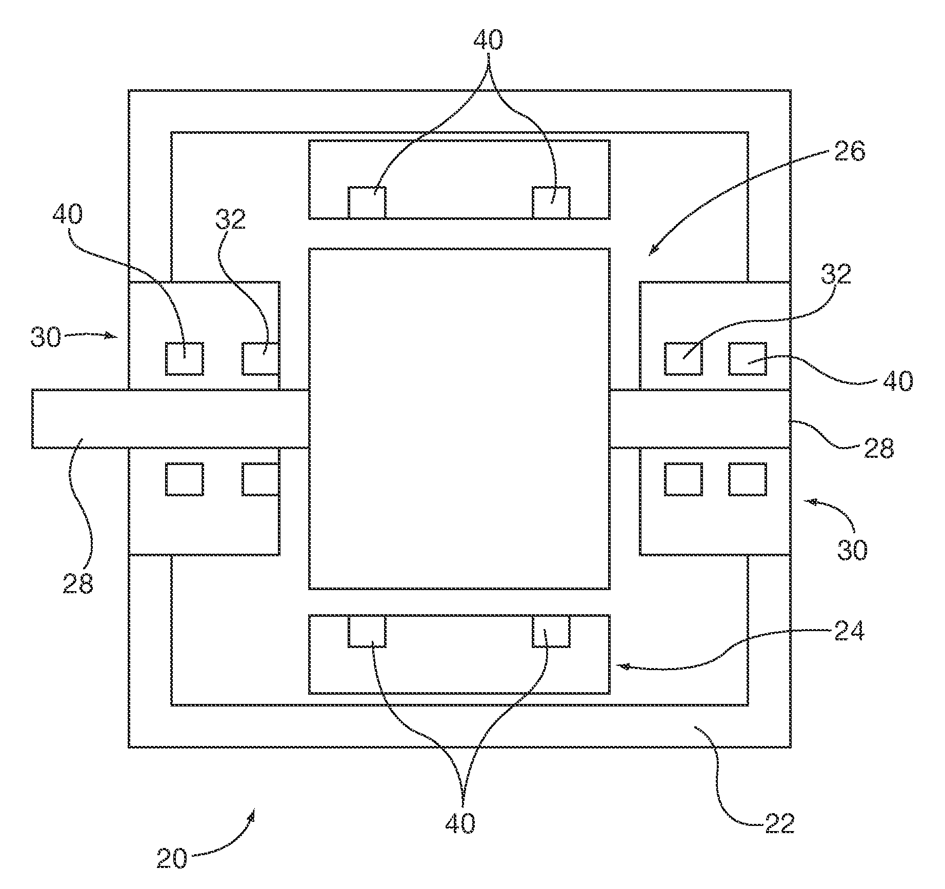
[0040]The permanent magnet axial thrust bearing 150 can be used in applications other than to support weight of a vertically oriented rotor shaft. For example, they may be applied to horizontally oriented shaft rotors directly on the shaft as a substitute for the embodiment 50 shown in FIGS. 7 and 8. Alternatively they may be applied to the rotor laminations as is shown in the induction machine embodiment of FIG. 1 by orienting the mounting bracket proximal and parallel to one or both ends of the rotor 26 lamination stack. In such an application the rotor laminations substitute for the electrical steel core 156.

[0041]FIG. 12 schematically depicts the magnetic fields and resultant magnetic forces Fr, Fu that are imparted on the vertically oriented rotor 126. As with other embodiments described herein, the resultant preload forces magnitudes and directions imparted on the vertical rotor shaft 128 can be selectively chosen for any given application.


PUM


Abstract

Permanent magnet bearings are incorporated into rotating equipment, such as induction machines, in addition to active magnetic or lubricated primary shaft support bearings. The passive magnetic bearings incorporate permanent magnets that generate directionally oriented magnetic fields of selective intensity. The magnetic field directions are aligned with a desired shaft support bearing preload direction and intensity, for example to exert axial thrust or radial preloads on the support bearings. A plurality of magnetic bearings may be oriented in opposed relationship with neutral or offsetting resultant forces. The passive magnetic force preload may be utilized to offset rotor vertical weight during induction startup or stopping cycles. Passive magnetic force preload may be applied to lubricated bearings to assure their operational stability. The passive magnetic bearings can also absorb radial or axial thrust forces imparted on the rotor shaft during induction machine operation, that may reduce machine operational noise, and energy consumption.

Description

BACKGROUND OF THE DISCLOSURE[0001]1. Field of the Invention[0002]The invention relates to induction machine and other rotating equipment bearings and more particularly methods and apparatus for exerting preload bias forces on induction machine lubricated or active magnetic bearings that support rotating shafts, through use of passive, permanent magnet bearings.[0003]2. Description of the Prior Art[0004]Known rotating equipment and induction machines, such as motors, often utilize lubricated mechanical bearings to support a rotating rotor. Exemplary lubricated bearing types include rolling element anti-friction bearings (e.g., ball- or roller-type) wherein the rolling elements are lubricated by a non-pressurized boundary film layer between the element and its associated bearing race, hydrodynamic journal or thrust bearings that generate self supporting pressurized lubricant films and hydrostatic bearings that employ externally pressurized lubricant.[0005]During motor or other rotatin...

Claims


Application Information

Patent Timeline
Patent Type & Authority Patents(United States)
IPC IPC(8): H02K7/09H02K7/08H02K5/16
CPCH02K7/09H02K5/161F16C25/045F16C32/0412F16C39/063F16C2380/26H02K17/00
Inventor LANG, NICHOLAS G.
Owner SIEMENS IND INC
Why Eureka
Try Eureka