
Paddle card with improved performance

a technology of improved performance and cable assemblies, applied in the direction of fixed connections, cross-talk/noise/interference reduction, coupling device connections, etc., can solve the problem of difficult to maintain such a profile, and achieve the effect of improving the termination structure and promoting beneficial termination

Active Publication Date: 2015-06-02
MOLEX INC
View PDF33 Cites 10 Cited by
  • Summary
  • Abstract
  • Description
  • Claims
  • Application Information

AI Technical Summary

Benefits of technology

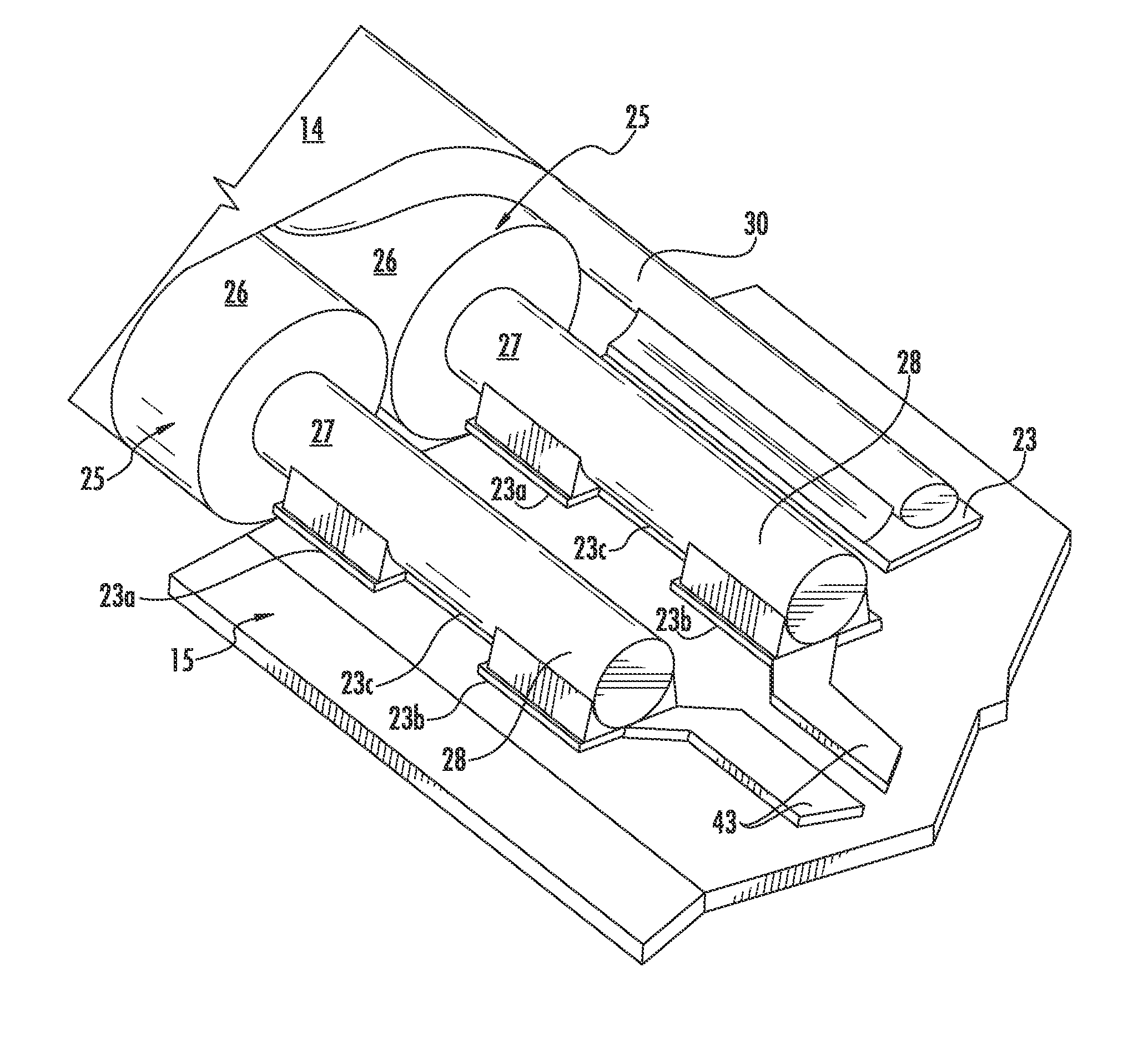
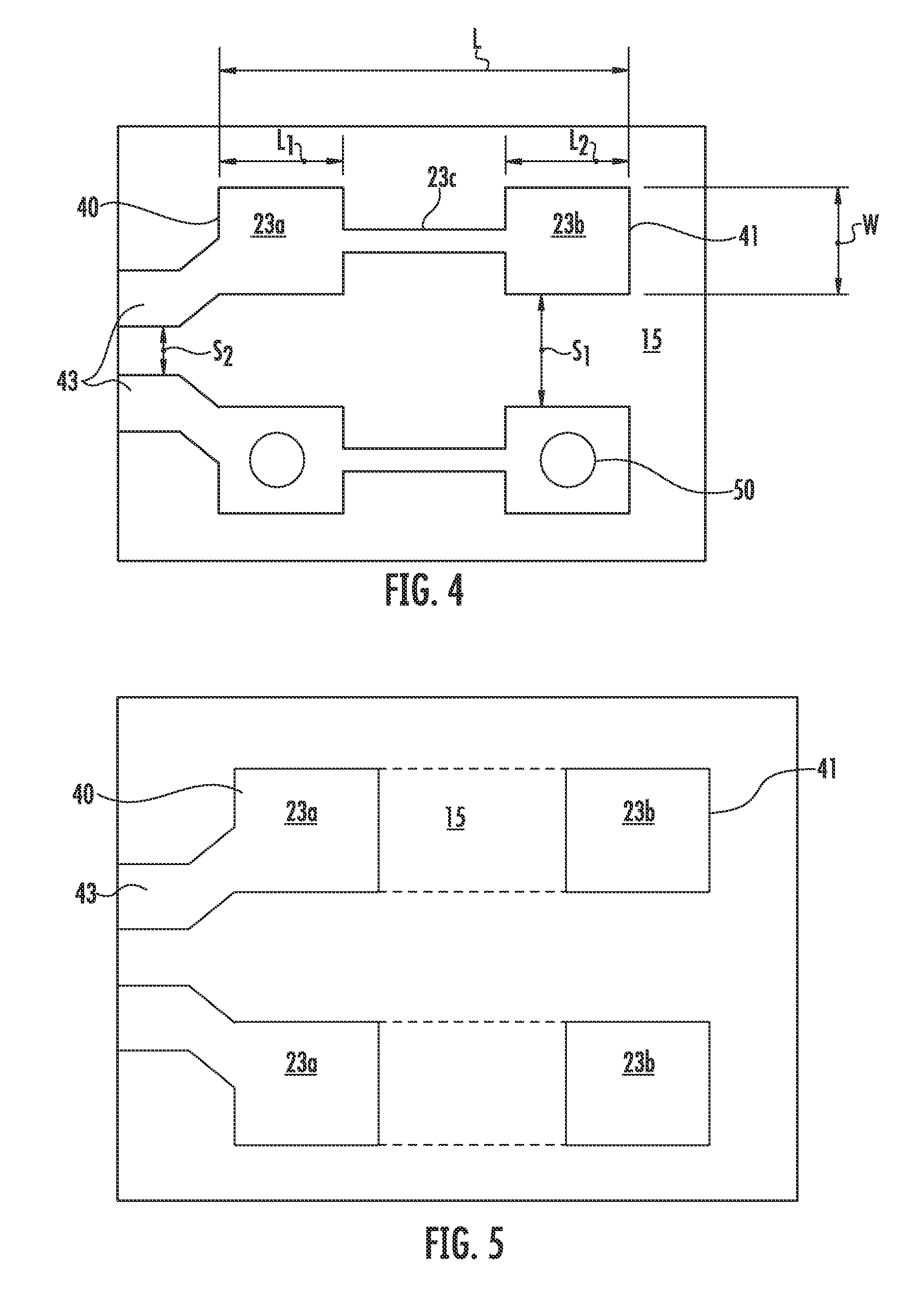
[0004]Accordingly, there is provided an improved paddle card having an improved termination structure which promotes beneficial termination in high speed data transmission applications.
[0006]The use of two contact pads in place of one elongated contact pad reduces the overall area of the termination structure for each wire terminated to the circuit board. Preferably, the two contact pads are spaced apart by an intervening spacing equal to or greater than that of one of the contact pads. The elimination of this extra conductive surface area reduces the capacitance, as compared to a regular, elongated rectangular contact pad, thereby reducing the impedance discontinuity that normally occurs in transition from the structured order of the cable wires to their termination on the surface of the circuit board. This modification of the impedance profile is important in that the circuit board termination area is prone to crosstalk, and flattening out the impedance discontinuity curve gives the cable and connector structure a better impedance profile and results in reduced crosstalk and electrical noise. In one of the embodiments of the Present Disclosure, the total length of the two contact pads may range between about 0.5 to about 0.8 of the total length between exterior ends of the contact pads. Similarly, the contact pads are preferably separated by an intervening distance of between about 20% to about 40% of the total length between the opposing edges of a pair of the contact pads.

Problems solved by technology

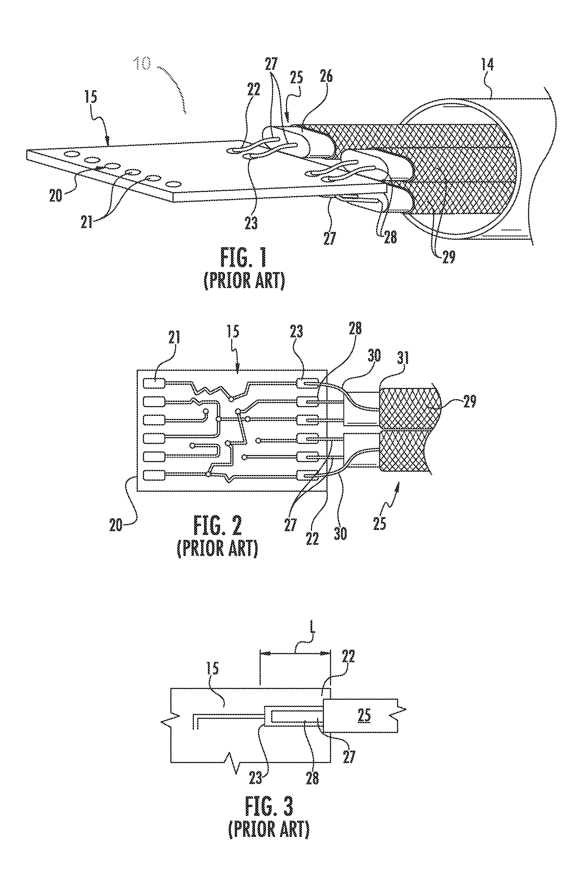
Most often, differential signal wires are used for each such transmission line in a cable and, although it is easy to maintain a desired impedance profile along the length of the cable due to the cable geometry, it is difficult to maintain such a profile where the wire ends are terminated to a circuit board or paddle card.

Method used


Image

  • Paddle card with improved performance
  • Paddle card with improved performance
  • Paddle card with improved performance

Examples


Embodiment Construction

[0019]While the Present Disclosure may be susceptible to embodiment in different forms, there is shown in the Figures, and will be described herein in detail, specific embodiments, with the understanding that the Present Disclosure is to be considered an exemplification of the principles of the Present Disclosure, and is not intended to limit the Present Disclosure to that as illustrated.

[0020]As such, references to a feature or aspect are intended to describe a feature or aspect of an example of the Present Disclosure, not to imply that every embodiment thereof must have the described feature or aspect. Furthermore, it should be noted that the description illustrates a number of features. While certain features have been combined together to illustrate potential system designs, those features may also be used in other combinations not expressly disclosed. Thus, the depicted combinations are not intended to be limiting, unless otherwise noted.

[0021]In the embodiments illustrated in ...


PUM


Abstract

A paddle card construction disclosed for use in connecting electronic devices together. The paddle card takes the form of a circuit board that has a plurality of conductive contact pads arranged thereon in pairs. The contact pads of each pair are spaced apart from each other to provide a pair of points to which cable wire free ends may be terminated, such as by soldering. The spacing of the pads apart from each other in effect reduces to amount of capacitance in the cable wire termination area on the circuit board, thereby reducing the impedance and insertion loss in that area at high frequencies. The contact pads of each pair may be further interconnected together by a thin, conductive trace that extends lengthwise between the contact pads.

Description

BACKGROUND OF THE PRESENT DISCLOSURE[0001]The Present Disclosure relates, generally, to cable interconnection systems, and, more particularly, to improved cable assemblies for use in high speed data transmission applications.[0002]Conventional cable interconnection systems are found in electronic devices, such as routers, servers and the like, and are used to form signal transmission lines. These transmission lines may extend between chip members and connectors, connectors in two different devices, and between devices themselves. Most often, differential signal wires are used for each such transmission line in a cable and, although it is easy to maintain a desired impedance profile along the length of the cable due to the cable geometry, it is difficult to maintain such a profile where the wire ends are terminated to a circuit board or paddle card. The wires are terminated to contact pads that are disposed on a surface of the circuit board. In such a situation, the exterior insulati...

Claims


Application Information

Patent Timeline
Patent Type & Authority Patents(United States)
IPC IPC(8): H05K1/09H01R9/03H01R13/6474H05K1/02
CPCH01R9/032H01R13/6474H05K1/0296H05K1/117H05K3/3405H05K2201/09381H05K2201/09727H05K2201/10356H01R13/65912H01R12/62H01R12/57H01R12/775H05K1/0216H05K1/111H05K1/112H05K2201/09218H05K2201/09418
Inventor BUGG, MARK ALAN
Owner MOLEX INC
Learn More