Mask cover assembly

a mask and assembly technology, applied in the field of mask cover assembly, can solve the problems of workers being exposed to large amounts of toxic materials, and exposed to serious diseases, and achieve the effect of suppressing the introduction of outside air or dust, and preventing the introduction of outside air

Inactive Publication Date: 2015-07-14
WOO JAE JONG +1
View PDF4 Cites 2 Cited by
  • Summary
  • Abstract
  • Description
  • Claims
  • Application Information

AI Technical Summary

Benefits of technology

[0018]Therefore, the present invention has been made in view of the above problems, and it is an object of the present invention to provide a mask cover assembly, in which a mask cover body and an exhaust valve are assembled to a mask main body provided as a disposable component, in which a face contact cushion member in the form of a multilayered cotton member is attached to an outer circumference of an inner surface of the mask main body so as to completely prevent invasion of fine dust, toxic gas and the like, in which inner and outer filters capable of strictly filtering contaminants and foul odors are installed to the exhaust valve so as to prevent deterioration in the functionality of the exhaust valve even after the exhaust valve has been repeatedly used for a long period of time and to prevent the wearer from inhaling the contaminants and foul odors, and in which the high price exhaust valve, the mask cover body and a band used to hang the mask on the wearer's face are reusable by allowing only the used mask main body to be disassembled and replaced, which results in a reduction in the price of the product.
[0019]It is another object of the present invention to provide a mask cover assembly, in which the size of a mask cover body can be adjusted by the wearer to conform to the size and the shape of the wearer's face, and in which in a state in which only a mask main body is located inside the mask cover body, an exhaust valve consisting of an exhaust valve cap and an exhaust valve body is axially inserted through an exhaust valve mounting aperture of the mask cover body and an aperture of the mask main body and is secured by means of a coupling member and thereafter, a safety shaft cap is assembled to a penetrating shaft of the exhaust valve cap to protect the wearer's face from the risk of a facial bruise.
[0021]The mask main body, which is assembled to an inner surface of the mask cover body between the exhaust valve body and the coupling member, may be formed by laminating non-woven fabric or cotton fiber in multiple layers and pressing and securing the same to each other. A soft face contact cushion member having a constant thickness may be attached to the circumference of an inner surface of the mask main body so as to come into contact with the wearer's face. The face contact cushion member may be formed by laminating cotton or gauze in multiple layers and pressing the resulting multi-layered structure to have a thickness in a range from 5 to 8 mm, thereby serving to prevent introduction of outside air or dust.
[0022]The mask cover body may be constructed by a plurality of meshed reinforcing structures to define the exhaust valve mount and the circumferential rim for pushing the mask main body. The circumferential rim acts to push the cushion member of the mask main body against the elasticity of the band, which can suppress introduction of outside air. A pair of band hanger portions may be integrally formed at opposite lateral positions of the rim of the mask cover body to enable the mask cover body to be worn on the wearer's face by means of holding bands caught by the band hanger portions. The band hanger portions may be provided with band length adjusting holes, which ensures that the length of the mask cover body can be adjusted to come into close contact with the wearer's face.
[0023]After a penetrating shaft of an exhaust valve cap, by which the mask cover body and the main mask body are assembled to each other, is assembled with the inner and outer filters, a thin rubber plate and the exhaust valve main body, a shaft cap may be coupled to a distal end of the penetrating shaft with an inner filter interposed therebetween. The shaft cap may serve not only to prevent the penetrating shaft sharply protruding from the mask cover body from causing injury to the wearer's face upon receiving external shock, but also to prevent separation of the plurality of components assembled to the penetrating shaft of the exhaust valve cap.

Problems solved by technology

In general, people who live in areas where dust is generated by environmental disruption, or workers who work in a variety of industrial sites, including paper mills, spinning plants, dye works, quarries and the like, which exhibit generation of a great amount of toxic matter, such as fine dust or toxic gas, are exposed to serious diseases by invasion of the toxic matter into the respiratory system.
In the event that workers have continuously inhaled such fine dust or toxic gas, the workers are liable to diseases, such as pulmonary diseases, respiratory diseases and the like.
Moreover, continuous inhalation of a great amount of fine dust or toxic gas into the lungs and the respiratory system may cause fatal damage to the human body.
However, most of these products have a relatively high price and require frequent replacement of a dust proof material because it inevitably exhibits deterioration in function after about 10 hours or more although this lifetime varies depending on an actual working time.
In addition, since most conventional dust proof masks have inferior filtering functions, disposable dust proof masks have been used in working sites that attach great importance to sanitation.
However, the above described prior art sanitary mask may fail to come into close contact at the rim of the mask main body with the wearer's face because of different face profiles of respective wearers.
Moreover, since the respective wearers have differences in the profile of the face and the height and curvature of the nose, the rim of the mask main body may have a greater space with the face around the nose, which may remarkably deteriorate the functionality of the mask.
Thus, after the mask is used two times in the morning and in the afternoon (for one day), reuse of the mask is impossible and the mask is disposed of as industrial waste.
However, the disclosed sanitary mask as described above has a disadvantage in that adjusting the holding band is not easy because it is designed to be hung on the ear.

Method used


Image

  • Mask cover assembly
  • Mask cover assembly
  • Mask cover assembly

Examples


Embodiment Construction

[0030]Hereinafter, an exemplary embodiment of the present invention will be described in detail with reference to the accompanying drawings.

[0031]In the drawings, it is noted that the same or similar elements are denoted by the same reference numerals as can as possible even though they are depicted in different drawings.

[0032]Additionally, in the following description of the present invention, a detailed description of known functions and configurations incorporated herein will be omitted when it may make the subject matter of the present invention unclear.

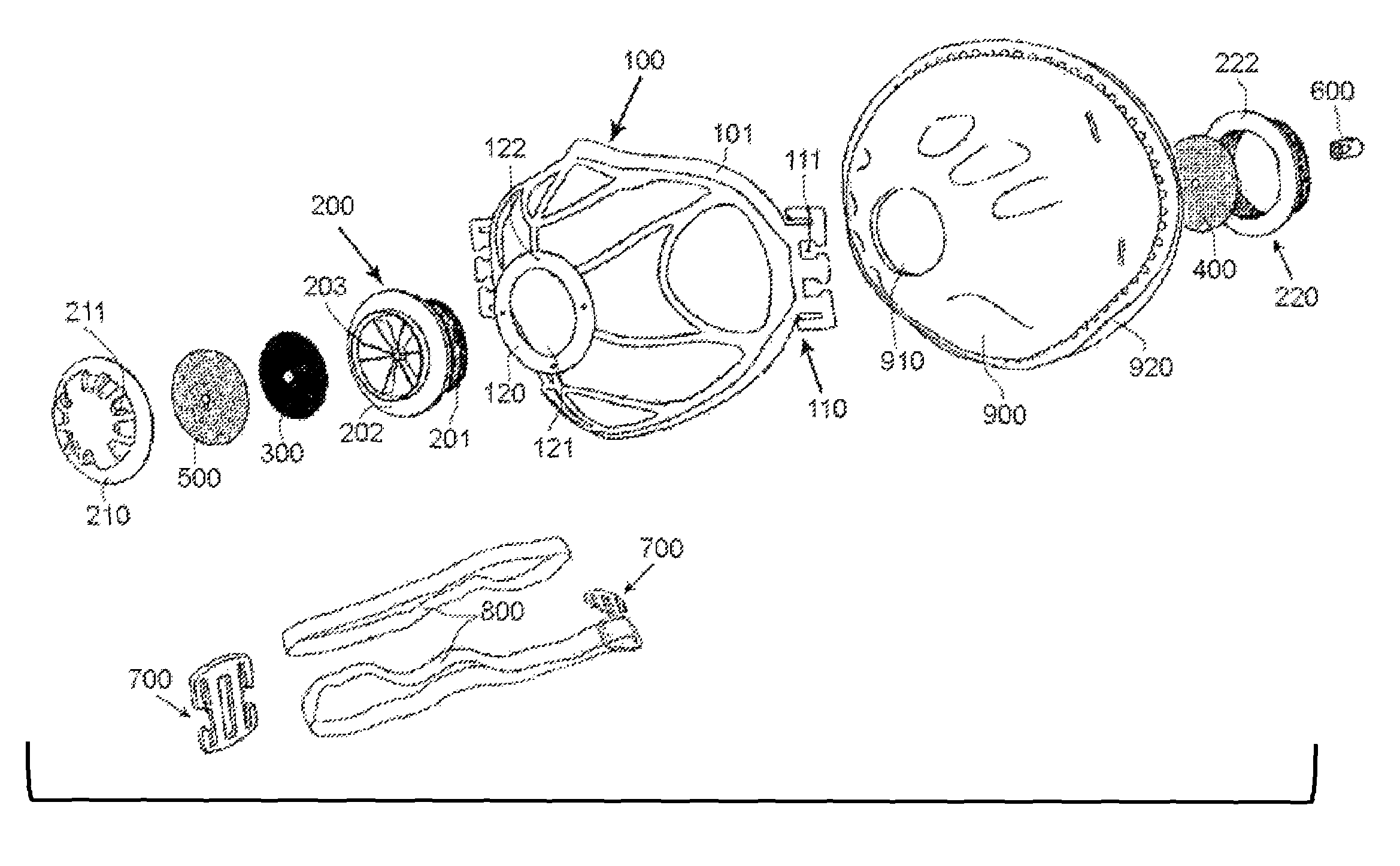
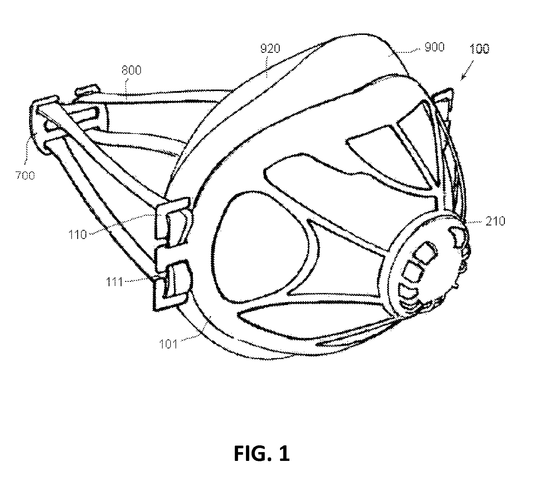
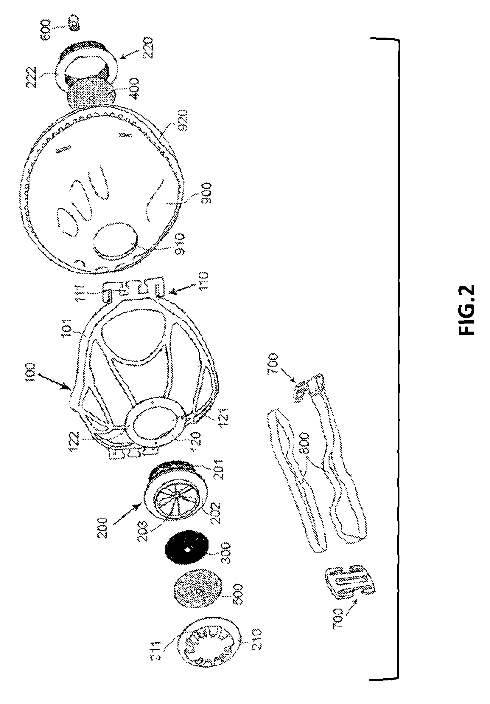
[0033]According to the exemplary embodiment of the present invention, an exhaust valve body 200, to which an exhaust valve cap 210, an outer filter 500 and a thin rubber plate 300 are axially coupled in sequence to constitute an exhaust valve, is axially inserted into a mask cover body 100 via a semi-spherical center exhaust valve mount 120 of the mask cover body 100. A mask main body 900 is assembled to an inner surface of the m...


PUM


Abstract

Disclosed is a mask cover assembly wherein a mask cover body is separably assembled with an exhaust valve and a mask main body, which enables replacement of the aforementioned elements. The mask main body has a semi-spherical cap form and is provided throughout the rim of an inner surface thereof with a face contact cushion member formed by pressing cotton or gauze to have a constant thickness. The mask cover body is configured to enclose the mask main body and is integrally formed at opposite lateral positions thereof with band hanger portions. The exhaust valve body is coupled to an exhaust valve mount of the mask cover body. An exhaust valve cap, an outer filter and a thin rubber plate are axially inserted into the exhaust valve body. Additionally, a coupling member is secured to the mask main body with an inner filter interposed therebetween.

Description

BACKGROUND OF THE INVENTION[0001]1. Field of the Invention[0002]The present invention relates to a mask cover assembly in which an exhaust valve including a valve body is separably assembled to a dust proof mask main body, which enables replacement of the mask main body.[0003]More particularly, the present invention relates to a mask cover assembly for use with a sanitary mask, a dust proof mask or other industrial masks that serve to protect a wearer from natural disasters, such as, e.g., generation of a great amount of dust due to environmental contamination, and industrial disasters, such as, e.g., generation of dust or particulate matter or toxic gas under harsh working conditions of industrial sites, in which an expensive exhaust valve can be repeatedly used, rather than being prepared as a disposable product, and a mask main body can be replaced alone when contaminated.[0004]2. Description of the Related Art[0005]In general, people who live in areas where dust is generated by ...

Claims


Application Information

Patent Timeline
Patent Type & Authority Patents(United States)
IPC IPC(8): A62B18/00A62B18/02A41D13/11A62B7/00A62B7/10A62B18/08
CPCA62B18/025A41D13/1138A62B7/10A62B18/084A62B18/02A62B23/02
Inventor WOO, JAE JONG
Owner WOO JAE JONG
Why Eureka
Try Eureka