Optical connector assembly

a technology of optical fiber cable and assembly, which is applied in the direction of optical elements, manufacturing tools, instruments, etc., can solve the problems of increasing signal attenuation and increasing the attenuation due to bending, and achieve the effect of increasing the signal attenuation and improving the attenuation of the optical fiber cable assembly

Active Publication Date: 2015-07-14
AMPHENOL CORP
View PDF22 Cites 2 Cited by
  • Summary
  • Abstract
  • Description
  • Claims
  • Application Information

AI Technical Summary

Benefits of technology

[0007]The inventors have recognized and appreciated that attenuation of an optical fiber cable assembly may be improved by use of a support mechanism for optical fibers within an optical connector terminating the cable assembly. Under temperature variation, the outer jacket of the cable has a tendency to shrink, which in turn, causes the optical fiber to be pushed out from the outer jacket and into the optical connector. This effect results in bunching of the optical fiber which leads to undue bending, eventually increasing signal attenuation.
[0008]Accordingly, aspects described herein relate to reducing the ability for the optical fiber extending from an optical cable to be bent within the connector in such a manner that leads to a consequential increase in attenuation over the operating temperature of the assembly. In some embodiments, an extension to an internal holding component of a connector may be formed with channels within which optical fibers may be routed and supported. Such an extension functions to support the normally exposed and unsupported fiber length that is disposed between the outer optical fiber jacket structure and an optical ferrule terminating the fiber or a ferrule holder into which such a ferrule is inserted.
[0010]As the optical fibers undergo various mechanical or environmental stresses, including those generated as the jacket of the optical fiber cable shrinks, the support member eliminates the ability for the optical fibers to bend excessively, which might otherwise result in an increase in attenuation due to bending. In some cases, the length of the support member occupies a region within the connector housing in which optical fiber are the typically unsupported, creating a guide for the optical fibers.
[0012]In another illustrative embodiment, an optical connector assembly is provided. The optical connector assembly includes a connector housing; an optical fiber jacket secured to the connector housing; a plurality of optical fibers, each of the plurality of optical fibers having a region disposed within the jacket and an exposed region, extending from the jacket and disposed within at least a portion of the connector housing; and a support member disposed adjacent to the jacket including a plurality of channels constructed and arranged to receive an exposed region of each of the plurality of optical fibers and prevent the exposed region of the plurality of optical fibers from substantial bending.
[0014]In a further illustrative embodiment, a method of operating an optical connector assembly. The method includes transmitting light between ends of a plurality of optical fibers; exposing the plurality of optical fibers to at least 80% of a temperature range between −40 C and 85 C; and preventing substantial bending of the plurality of optical fibers during exposure to the at least 80% of the temperature range between −40 C and 85 C.

Problems solved by technology

Under temperature variation, the outer jacket of the cable has a tendency to shrink, which in turn, causes the optical fiber to be pushed out from the outer jacket and into the optical connector.
This effect results in bunching of the optical fiber which leads to undue bending, eventually increasing signal attenuation.
As the optical fibers undergo various mechanical or environmental stresses, including those generated as the jacket of the optical fiber cable shrinks, the support member eliminates the ability for the optical fibers to bend excessively, which might otherwise result in an increase in attenuation due to bending.

Method used


Image

  • Optical connector assembly
  • Optical connector assembly
  • Optical connector assembly

Examples


Embodiment Construction

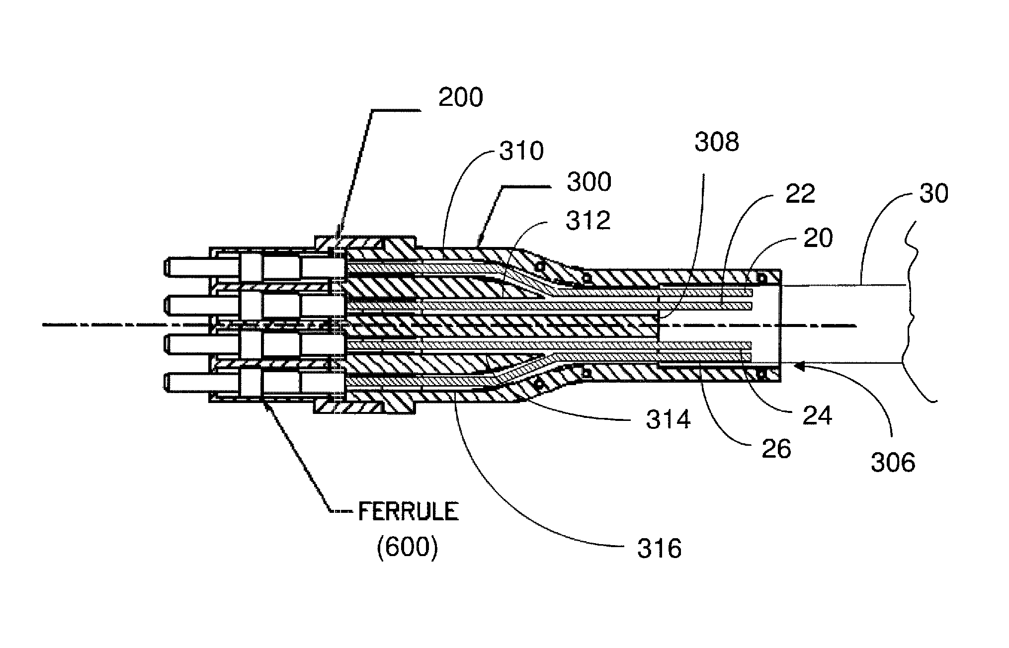
[0032]Optical fiber connections are often placed outdoors and, accordingly, experience wide variations in temperature over the course of their lifetime. The inventors have recognized an appreciated that operation of an optical fiber cable assembly in an environment subject to temperature variations can be improved through incorporation of a support member in a connector terminating the cable assembly. A member, appropriately shaped and positioned within a connector, supporting exposed fibers may reduce attenuation in the cable assembly.

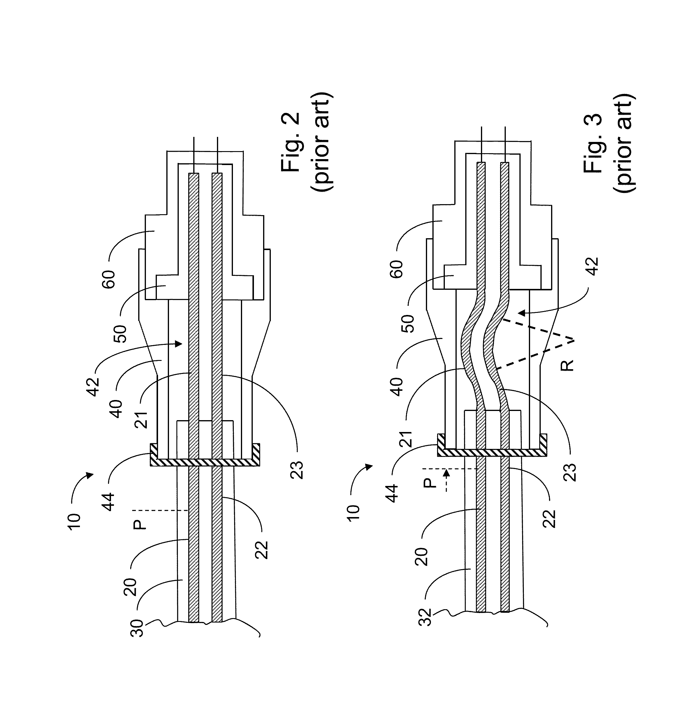
[0033]Though not being bound by any particular theory of operation, the inventors believe that such a support member may reduce macrobending, and therefore attenuation, in optical fibers that extend from the protective jacket of the cable to be terminated within a housing of the connector. Such macrobending might otherwise result from different temperature outer jacket of an optical cable experiences shrinkage by a greater amount than the optical fibe...


PUM

PropertyMeasurementUnit
diameteraaaaaaaaaa
bend radiusaaaaaaaaaa
diameteraaaaaaaaaa

Abstract

An optical connector for reducing attenuation in a cable assembly. A support within the connector precludes bending of exposed fiber within the connector that might otherwise occur when the cable assembly is exposed to environmental conditions involving cyclic temperatures. In some embodiments, optical connector assemblies include an optical fiber jacket surrounding a plurality of optical fibers and a support member adjacent to the jacket. The support member includes channels for receiving regions of the optical fibers that are exposed exterior to the optical fiber jacket. The channels of the support member serve to prevent severe bending of the optical fibers which otherwise would give rise to significant signal attenuation. For multi-fiber optical connector assemblies described herein, even during harsh environmental conditions, the signal loss in the optical fibers may be less than about 0.5 dB. The support may be formed as an extension of a ferrule holder.

Description

BACKGROUND[0001]1. Field of Invention[0002]Aspects described herein relate generally to a method and apparatus for reducing attenuation of light within an optical fiber cable assembly.[0003]2. Discussion of Related Art[0004]Modern life is full of devices that process information in digital form. Computers share digital information over the Internet or other computer networks. Information, such as radio and television signals, that in the past was communicated as analog signals is now frequently digitized and communicated over networks. For example, many homes have a high speed digital connection to a cable company or other service provider.[0005]The increased use of digital information has created a need for reliable interconnection systems that can connect devices and networks that generate or consume digital information. One form of interconnection system employs optical fiber for transmission of digital information. Large amounts of information can be encoded as a light signal, w...

Claims


Application Information

Patent Timeline
Patent Type & Authority Patents(United States)
IPC IPC(8): G02B6/26G02B6/36G02B6/14G02B6/38
CPCG02B6/36G02B6/262G02B6/3878G02B6/14G02B6/3636G02B6/387G02B6/3887Y10T29/49826G02B6/38875G02B6/3888
Inventor CHEN, MINNGUYEN, ANH NGOCBALTRUKONIS, DARIJUS
Owner AMPHENOL CORP
Why Eureka
Try Eureka