Ultrasonic transducer for use in a fluid medium

a technology of ultrasonic transducers and fluid mediums, which is applied in the direction of liquid/fluent solid measurements, machines/engines, instruments, etc., can solve the problems of difficult handling during the construction process, inability to use the transducer sleeves, and only being able to contact piezoceramic suitable for mass production, etc., to achieve the effect of simplifying the construction of the ultrasonic transducer

Inactive Publication Date: 2015-07-21
ROBERT BOSCH GMBH
View PDF15 Cites 6 Cited by
  • Summary
  • Abstract
  • Description
  • Claims
  • Application Information

AI Technical Summary

Benefits of technology

[0010]Furthermore, the ultrasonic transducer includes at least one housing. This housing may be implemented as sleeve-shaped in particular. A housing is understood as an element which terminates the ultrasonic transducer essentially at the outside and gives the ultrasonic transducer its essential shape at the outside. The housing, as explained in greater detail below, may in particular be manufactured from a metallic material and / or a plastic material and may protect the ultrasonic transducer against external mechanical and / or chemical influences and / or against temperature and / or pressure influences.
[0011]One idea of the present invention is that the assembly and the construction of the ultrasonic transducer may be simplified significantly if the housing is implemented in at least two parts. Correspondingly, the housing has at least two housing parts. These housing parts are preferably implemented completely separately and accordingly may preferably be manufactured and / or handled completely independently of one another.
[0017]The electroacoustic transducer element may in particular be aligned flush with the first housing part or protrude beyond the first housing part on the side, which faces away from the fluid medium. This embodiment is particularly advantageous to ensure simple electrical contacting of the electroacoustic transducer element.
[0021]As explained above, the transducer core may include additional elements in the at least one electroacoustic transducer element. For example, the transducer core may include at least one adjusting body, for example, according to the above-described related art. This adjusting body may improve an acoustic coupling between the electroacoustic transducer element and the fluid medium. The first housing part may at least partially surround the adjusting body, for example, enclose it in a ring-shaped manner.
[0030]The proposed ultrasonic transducer and the proposed method have numerous advantages over known ultrasonic transducers and known manufacturing methods. Thus, a foundation is formed for a cost-effective ultrasonic transducer, which is manufacturable in mass production, for example, an air ultrasonic transducer, as may be used for gas flow measurement in the automotive field, for example. An ultrasonic transducer may be used as an ultrasonic flow meter on the pressure side of turbocharged internal combustion engines, for example.
[0031]The ultrasonic transducer may be constructed simply and cost-effectively. Thus, the ultrasonic transducer may be manufactured on the basis of a piezoceramic, optionally having an impedance adjustment layer, having a housing in the form of a two-part sleeve, for example. The first housing part may be implemented as the front-side part of the sleeve and may be connected to the adjustment layer. This connection may occur via at least one decoupling element and / or at least one sealing film and / or a coating and / or a combination of these elements, for example. The first housing part, for example the front-side part of the entire sleeve, may be implemented as flat in such a way that the rear side of the piezo is located approximately in one plane together with the rear sleeve edge. The piezo may accordingly be well accessible during the installation, gluing, and contacting processes. The second housing part may in particular be implemented as the rear-side sleeve part. This second housing part may be implemented as a deeper sleeve part than the first housing part. The second housing part may accordingly accommodate a damping and / or a decoupling and / or a supporting material as described above, for example a molding material.

Problems solved by technology

In practice, this type of assembly is, however, associated with various technical requirements and disadvantages in practice.
However, the handling during the construction process is typically made more difficult by this depth of the transducer sleeve, because the piezoelement must be sunk deep into the transducer sleeve.
Electrical contacting of the piezoceramic which is suitable for mass production is then only possible with difficulty inside the sleeve.
Such a method is extraordinarily complex.

Method used


Image

  • Ultrasonic transducer for use in a fluid medium
  • Ultrasonic transducer for use in a fluid medium
  • Ultrasonic transducer for use in a fluid medium

Examples


Embodiment Construction

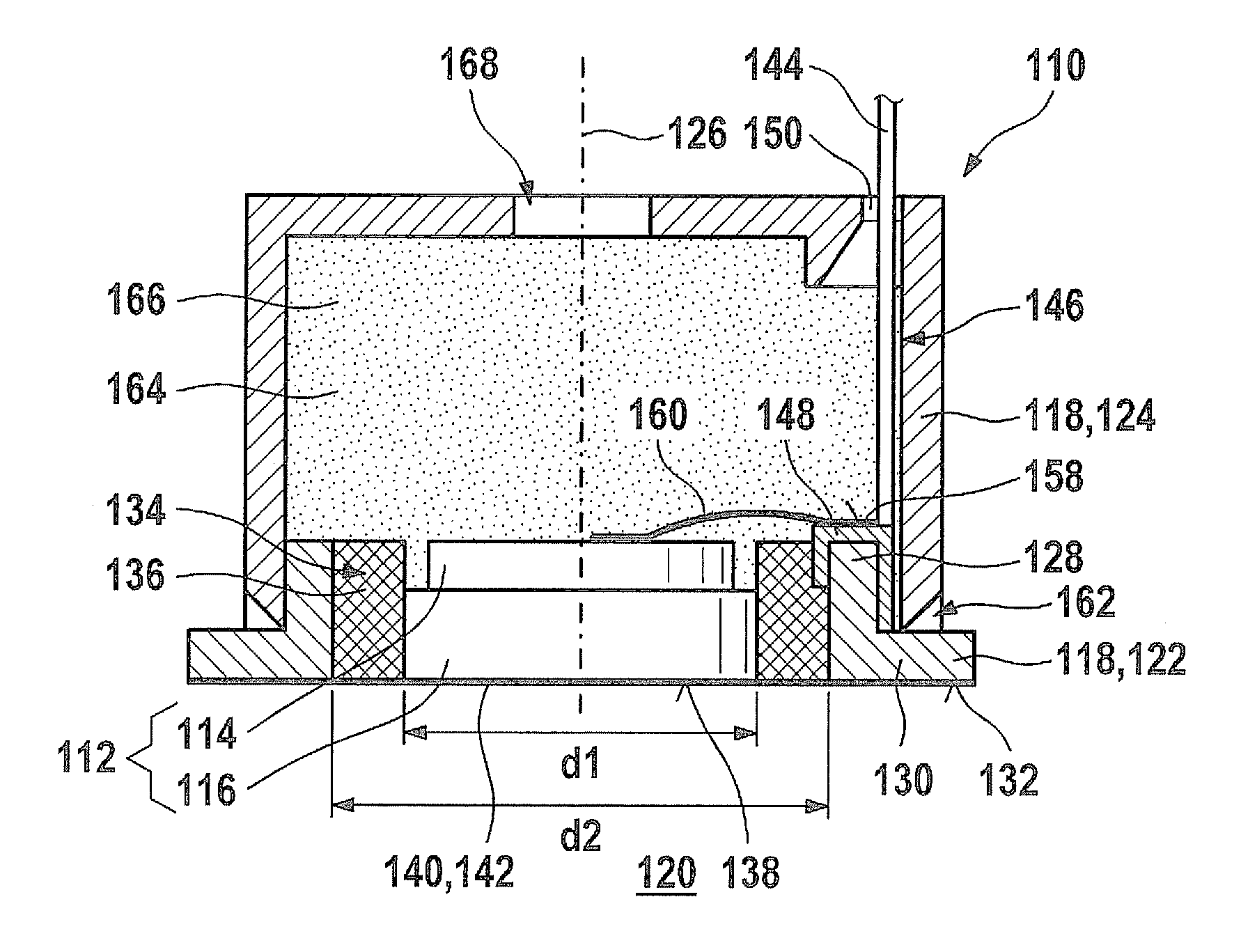
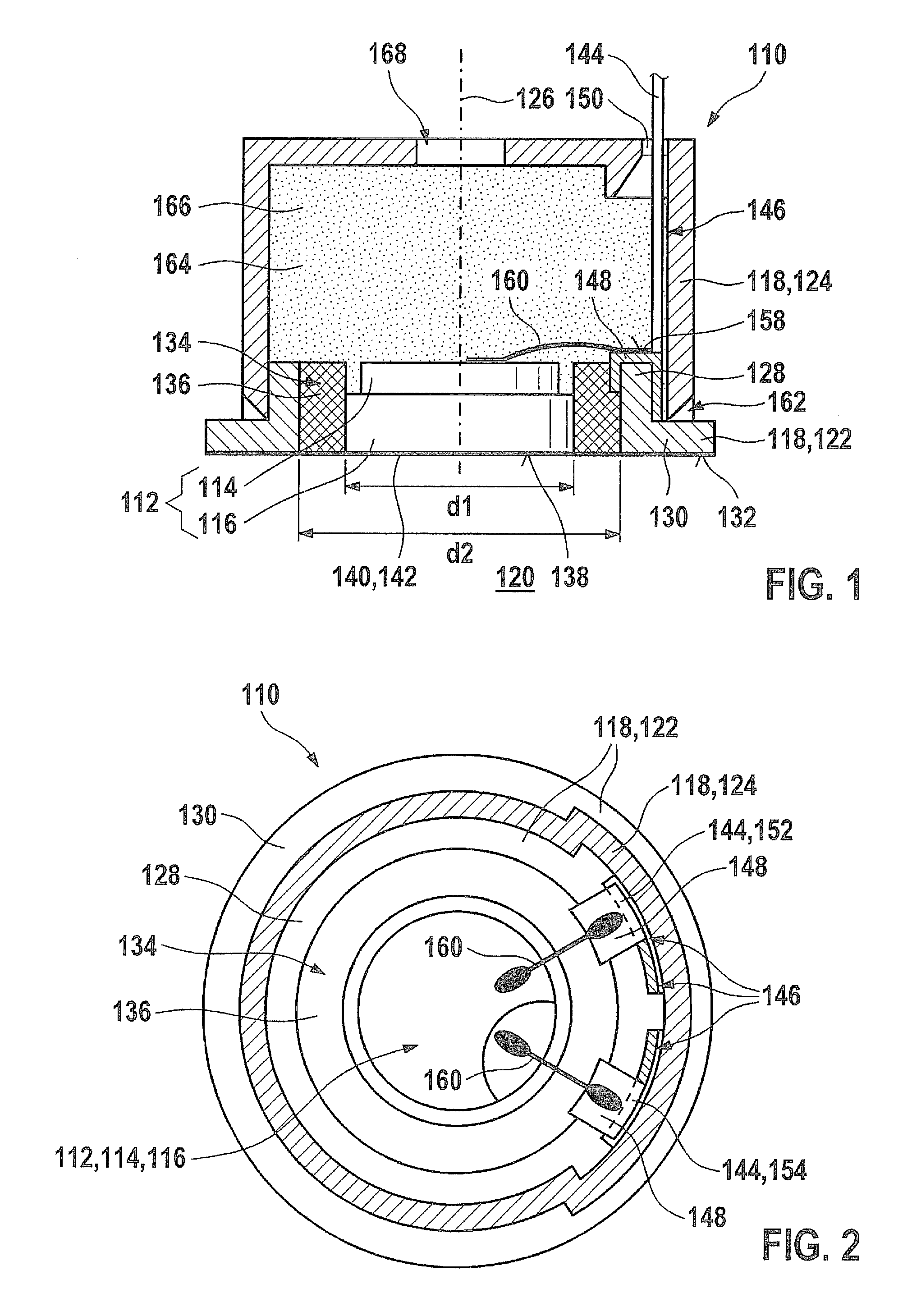
[0036]One possible exemplary embodiment of an ultrasonic transducer 110 according to the present invention is shown in FIGS. 1 and 2. FIG. 1 shows a sectional view from the side, while in contrast FIG. 2 shows a sectional view perpendicular to the sectional plane in FIG. 1 in the top view. Ultrasonic transducer 110 includes a transducer core 112, which in turn includes an electroacoustic transducer element 114 and an adjusting body 116. Adjusting body 116 may be implemented, for example, as a λ / 4 impedance adjustment layer. Electroacoustic transducer element 114 may be implemented, for example, as a piezoelement and may be connected directly or via at least one intermediate layer (for example, an intermediate layer to compensate for thermomechanical tensions) to adjusting body 116. In the illustrated exemplary embodiment, adjusting body 116 has a slightly greater diameter d1 than electroacoustic transducer element 114. For example, entire transducer core 112 may therefore have diame...


PUM

PropertyMeasurementUnit
diameteraaaaaaaaaa
internal diameter d2aaaaaaaaaa
thicknessaaaaaaaaaa

Abstract

An ultrasonic transducer for use in a fluid medium includes at least one transducer core having at least one electroacoustic transducer element, and further includes at least one housing having at least two housing parts. At least one first housing part at least partially encloses the transducer core such that a rear side of the electroacoustic transducer element which faces away from the fluid medium is accessible. Furthermore, at least one second housing part is connected to the first housing part. The ultrasonic transducer is essentially terminated by the second housing part on its side, which faces away from the fluid medium.

Description

BACKGROUND OF THE INVENTION[0001]1. Field of the Invention[0002]The present invention relates to an ultrasonic transducer for use in a fluid medium.[0003]2. Description of Related Art[0004]Ultrasonic transducers are known in various fields of use from the related art. For example, ultrasonic transducers are used in automotive engineering in ultrasonic flow meters, for example, in the exhaust system and / or in the intake system of internal combustion engines. Examples of such ultrasonic transducers are described in published German patent application document DE 10 2007 037 088 A1 or German Patent Application DE 10 2008 055 126.0 of the applicant (which is not believed to be prior art). Ultrasonic flow meters are based in many cases on two ultrasonic transducers, which are situated offset in a flow tube in the flow direction and mutually send one another ultrasonic signals. Measuring systems may also be used in which at least one reflector is provided, for example, in the form of plug...

Claims


Application Information

Patent Timeline
Patent Type & Authority Patents(United States)
IPC IPC(8): G10K9/122G01N29/24G01F23/296G10K9/22
CPCG10K9/122G01F23/296G01F23/2968G01N29/2437G10K9/22Y10T29/49005
Inventor MUELLER, ROLANDHUEFTLE, GERHARDHORSTBRINK, MICHAELLANG, TOBIASRADWAN, SAMIKUENZL, BERNDWANJA, ROLAND
Owner ROBERT BOSCH GMBH
Why Eureka
Try Eureka