Coupling arrangement for non-axial transfer of electromagnetic radiation

a non-axial transfer and electromagnetic radiation technology, applied in the direction of instruments, electrical appliances, basic electric elements, etc., can solve the problems of splicing between the tapered fibers, weak degradation of the beam quality of the laser, and the tapering process of the feeding fiber and the signal fiber, so as to achieve the effect of increasing the coupling efficiency

Active Publication Date: 2015-08-04
LASER ZENT HANNOVER
View PDF20 Cites 2 Cited by
  • Summary
  • Abstract
  • Description
  • Claims
  • Application Information

AI Technical Summary

Benefits of technology

[0011]It is thus an object of the present invention to provide a coupling arrangement with an increased coupling efficiency even with feeding fibers comprising a glass cladding.
[0012]It is a further object of the invention to provide a coupling arrangement in which the tapering of the target fiber has less negative effects on the optical characteristics of the target fiber and the coupling arrangement.
[0013]It is still a further object of the invention to provide a method to produce a coupling arrangement leading to a smaller taper-ratio of the target fiber without the necessity to pre-taper the feeding fibers.

Problems solved by technology

The first disadvantage is the splice between the tapered fibers and the target fiber, where the fibers to be connected have to be aligned very exactly.
For example, a small misalignment can lead to a strong degradation of the beam quality of the laser.
The second disadvantage is the tapering process of the feeding fibers and the signal fiber to match the optical requirements of the core and the cladding of the target fiber.
For example, a small taper mismatch can lead to a significant thermal load of the fiber coupler and also to a strong degradation of the beam quality of the laser.
Another disadvantage is that due to existence of only two target fiber end surfaces the number of pump feeding fibers is limited.
Thus, the laser power can not be simply scaled up by using more pump diodes.
Due to losses and inefficiencies not all of the pump radiation can be transferred from the feeding fibers into the target fiber.
This lost power results in a heating of the coupling arrangement and thus limits the maximum amount of radiation power that can be transferred through a coupling arrangement.
This unfortunately in practice is rather difficult, since in many cases both the core and the cladding consist of almost the same material differing only by some doping elements.
Hence, it is difficult to remove the cladding for example using an etching technique, and stop the etching when the cladding is fully removed and the core has not been damaged.
Increasing the taper-ratio leads to a better transfer of electromagnetic radiation from the feeding fiber into the target fiber but reduced the mechanical stability of the coupling arrangement.
Unfortunately the target fiber also shows a converging taper portion and a diverging taper portion after an arbitrary longitudinal irreversible extension, leading to changed optical characteristics of the fiber.
The disadvantage is that the pre-tapered feeding fiber becomes very damageable due to the reduced diameter.

Method used


Image

  • Coupling arrangement for non-axial transfer of electromagnetic radiation
  • Coupling arrangement for non-axial transfer of electromagnetic radiation
  • Coupling arrangement for non-axial transfer of electromagnetic radiation

Examples


Embodiment Construction

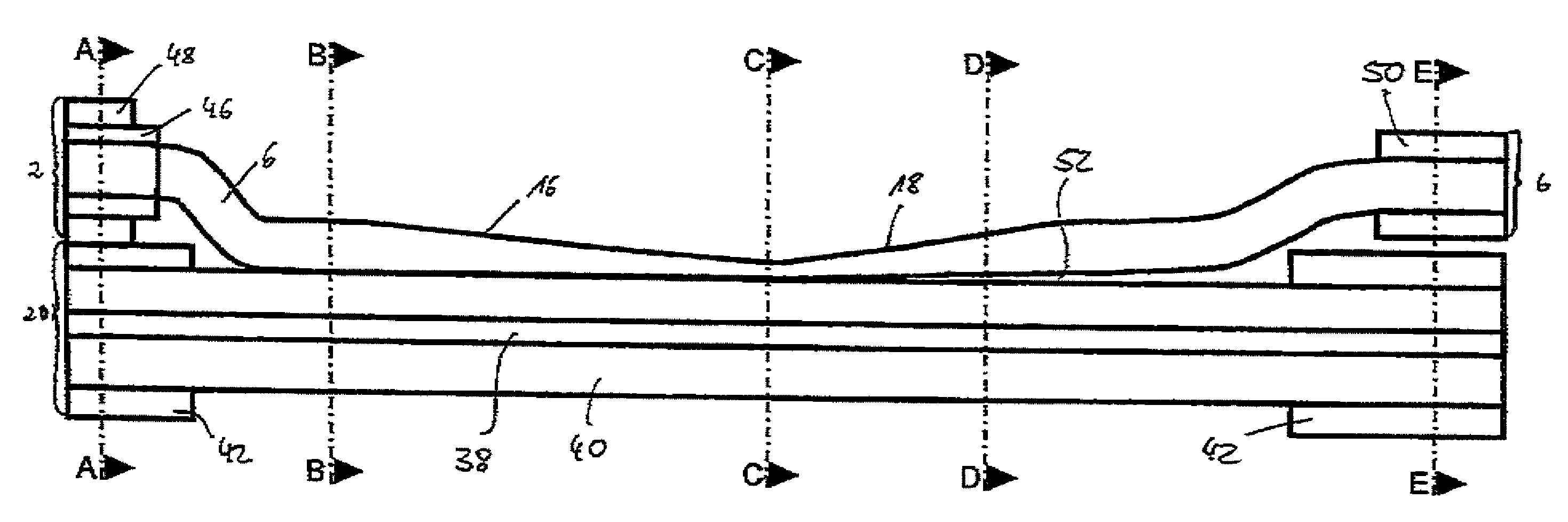
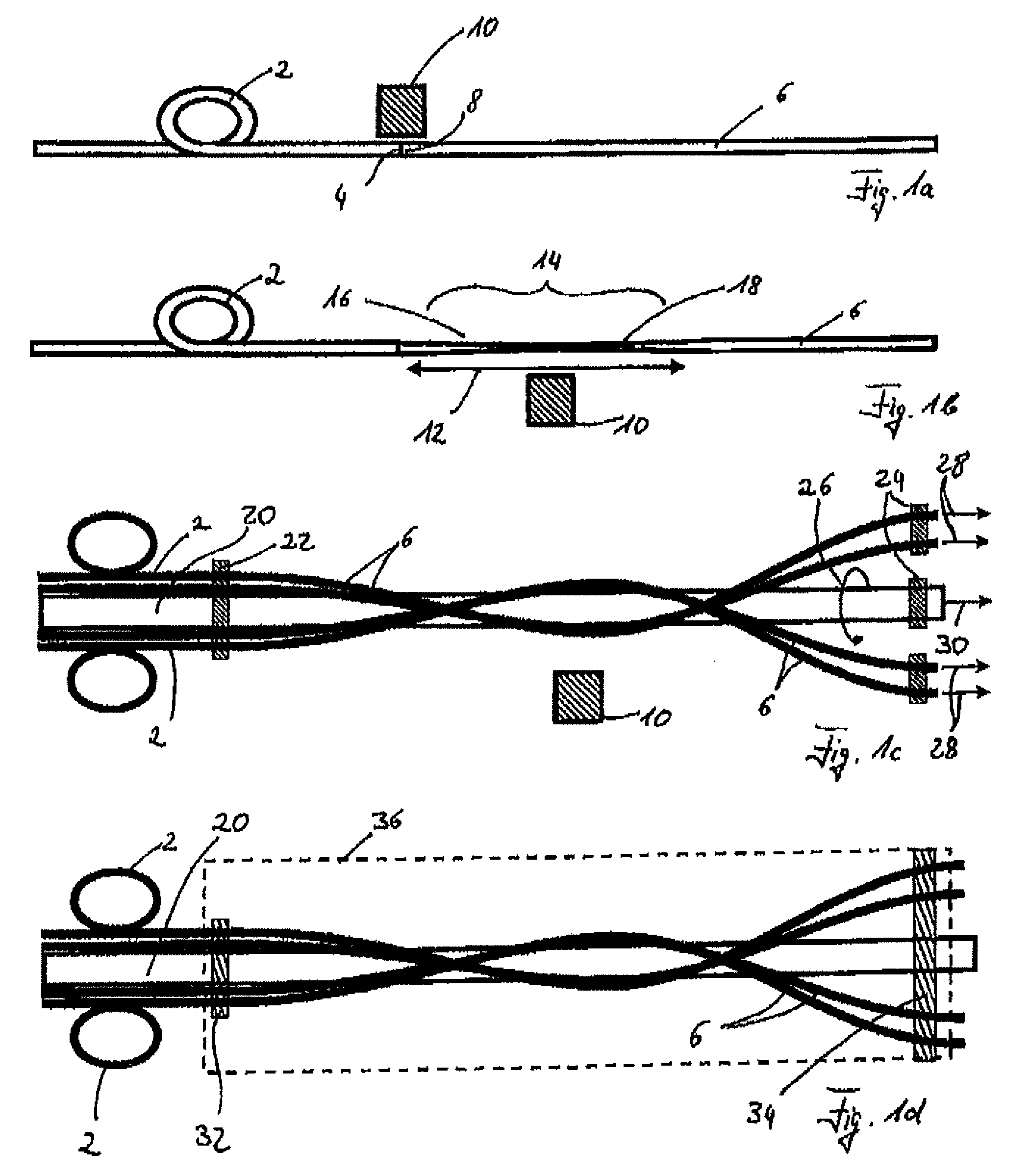
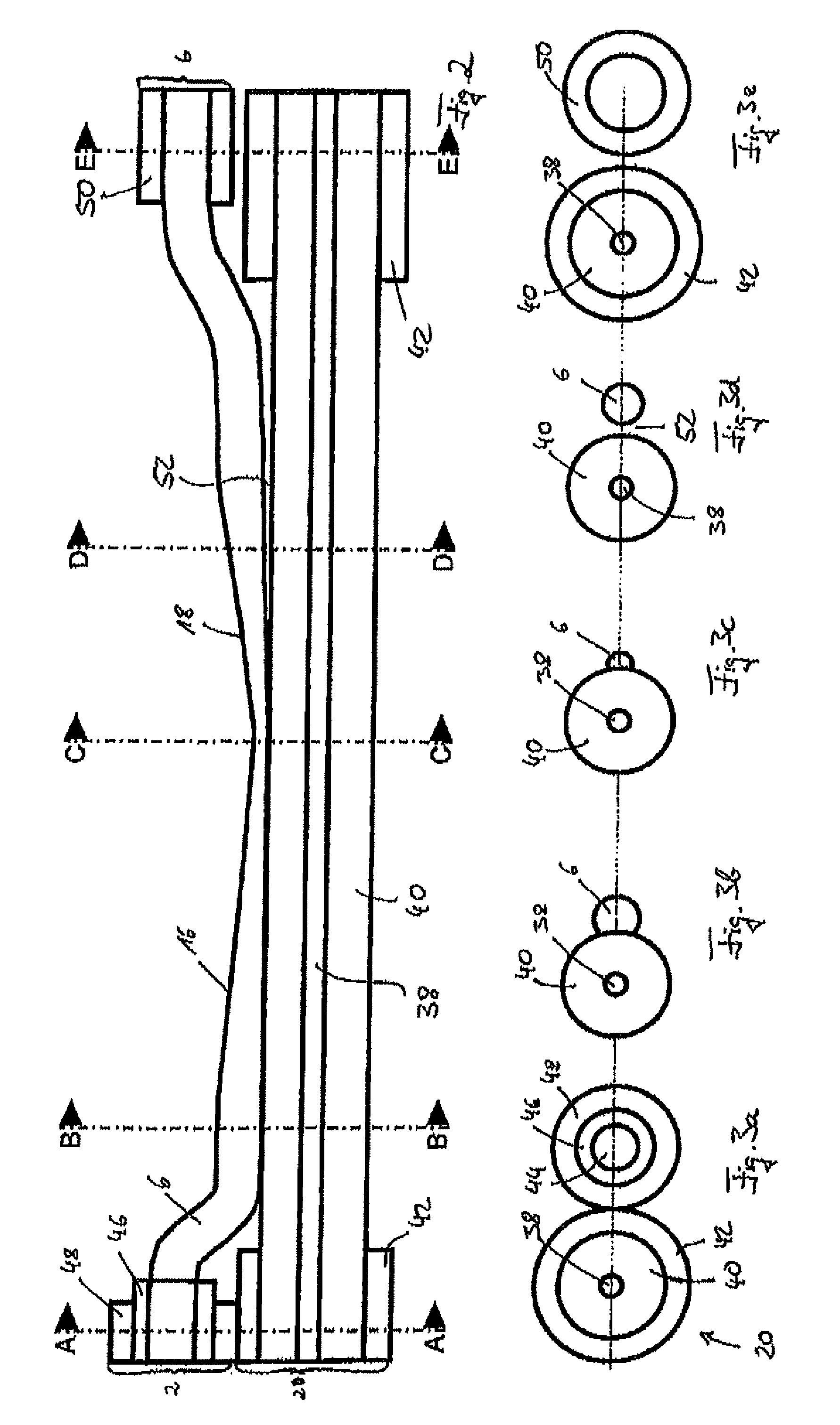
[0055]Throughout the description same reference numbers are used to denote same parts.

[0056]FIG. 1a to 1d show different steps of a method according to one embodiment of the present invention. FIG. 1a shows a feeding fiber 2 with an output end 4, which is connected with an intermediate fiber 6. The intermediate fiber 6 is fusion spliced to the output end 4 of the feeding fiber 2 with its input end 8. Schematically a heat source 10 is shown, which can for example be a micro gas flame, a plasma source, a filament source or a laser. The heat source 10 is used to heat the intermediate fiber 6 until a given temperature is reached. The heat source 10 can move along the longitudinal position of the intermediate fiber 6, which is to be heated. By the length of this movement the length of the converging taper portion can be adjusted. The heat source 10 moves along the intermediate fiber 6 with a certain frequency in a back and forth movement. This can be achieved by moving the heat source 10...


PUM

PropertyMeasurementUnit
thicknessaaaaaaaaaa
cladding diameteraaaaaaaaaa
diameteraaaaaaaaaa

Abstract

A coupling arrangement according to the present invention comprises a target fiber, at least one feeding fiber and an intermediate fiber. The intermediate fiber comprises an input end and a converging taper portion, wherein the input end of the intermediate fiber is spliced to an output end of the feeding fiber in an axial way. Due to this coupling electromagnetic radiation being fed through the feeding fiber enters the intermediate fiber through its input end surface. The converging taper portion of the intermediate fiber is fused to the target fiber in the transfer region in a non-axial way. This leads to a non-axial coupling such that electromagnetic radiation, which entered the intermediate fiber through the input end surface thereof, is coupled into the target fiber.

Description

FIELD OF THE INVENTION[0001]The invention relates to coupling arrangements for non-axial transfer of electromagnetic radiation from at least one feeding fiber to a target fiber in a transfer region. With this kind of coupling arrangement it is possible to couple multi-mode pump fibers, which in the following are referred to as feeding fibers, into the outer cladding of single-clad or multi-clad fibers, which in the following are called target fibers.BACKGROUND OF THE INVENTION[0002]Multimode optical fibers are used in many applications especially for delivering optical power. One of the most interesting applications is the so called fiber laser. In the case of a fiber laser the double-clad fiber (DCF) concept is mostly used. A DCF consists of a core to guide the laser light, surrounded by a cladding to guide the multi-mode pump light. Such a DCF, which is one of the possible optical target fibers, comprises a core, which has a relatively small diameter of for example 5 to 60 μm. It ...

Claims


Application Information

Patent Timeline
Patent Type & Authority Patents(United States)
IPC IPC(8): G02B6/26G02B6/28
CPCG02B6/2835Y10T29/49174
Inventor THEEG, THOMAS
Owner LASER ZENT HANNOVER
Why Eureka
Try Eureka