Second generation low-cost particle counter

a particle counter and low-cost technology, applied in the direction of material analysis, withdrawing sample devices, instruments, etc., can solve the problems of affecting the final unit cost, and requiring a large amount of equipment, etc., to achieve the effect of low cost, low weight and low power consumption

Active Publication Date: 2015-08-25
ALPHASENSE LTD
View PDF16 Cites 9 Cited by
  • Summary
  • Abstract
  • Description
  • Claims
  • Application Information

AI Technical Summary

Benefits of technology

[0030]As this detector assembly requires only a single reflector or refractor means and a single detector means this may have the effect of providing a low cost apparatus for counting and sizing particles which operates by providing an optically defined rather than physically defined (by for example, a narrow fluid delivery tube) particle sensing zone in which particles are detected. The dual optical sensing zone allows not only for particles to be detected but also to be counted and sized accurately. In situations where there is an existing airflow (eg: the apparatus is attached to a moving vehicle or aircraft or is moved by hand through the air) in a direction relative to the broad axis of the elliptical cross-section laser beam, the apparatus is able to operated without the need of a pump to draw a sample through a narrow chamber, as in conventional optical particle counters. Given that there is no pump and that the apparatus parts are simple, light and cheap to construct, this apparatus provides a low cost hand held device with single particle sensitivity. Furthermore, as this detector assembly requires only a single reflector or refractor means and a single detector means this may have the further effect of allowing the single reflector or refractor means and single detector means combination to be placed at any angle in the plane containing the broad axis of the laser beam, providing the mirror or detector do not obstruct the beam of radiation.
[0063]The present invention seeks to provide a method of aerosol monitoring (having single particle sensitivity) which requires no air-pump or particle filter, and which is mechanically very simple, thus offering the prospect of manufacture using a small number of injection-moulded plastic parts. The air-movement may be achieved using a small electrical fan (far lower current consumption than a rotary-vane or diaphragm air-pump), by exploiting the natural movement of the ambient air (e.g.: wind, convection flow, etc.), or by simply moving the sensor unit itself through the air by hand or by attaching to a moving vehicle (car, train, aircraft, etc).

Problems solved by technology

These features of conventional OPC's result in several drawbacks; firstly, the pumps used must overcome the pressure drops in the sample tube and particle filter, and this has implications for pump size and current consumption (and, by extension, for battery-life in standalone of hand-held units); secondly, the particle filters need to be periodically replaced (incurring further cost to user); and thirdly, the air sample handling system comprising sample inlet tube, vent tube, interconnecting tubing and filter, etc.), can be relatively complex to manufacture and assemble, with implications for final unit cost.
A problem with this device is that the detector is not able to distinguish the number or size of particles passing through the, rather large, detection zone.
This device is only able to detect that at least one particle has passed through the detection zone, and in this regard it is little more than a portable smoke detector.
This device cannot be used to accurately count the number of particles passing through the detection zone

Method used


Image

  • Second generation low-cost particle counter
  • Second generation low-cost particle counter
  • Second generation low-cost particle counter

Examples


Embodiment Construction

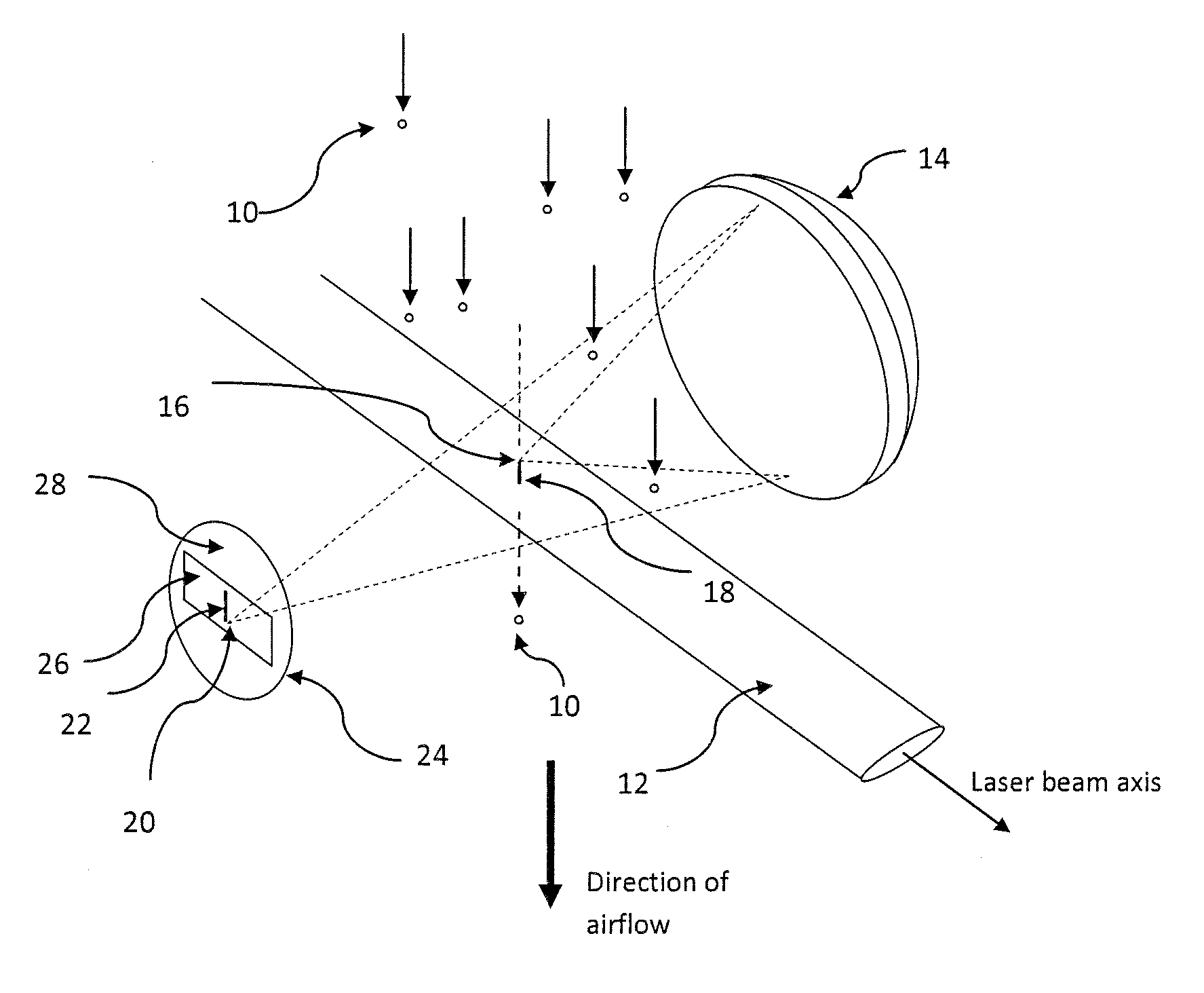
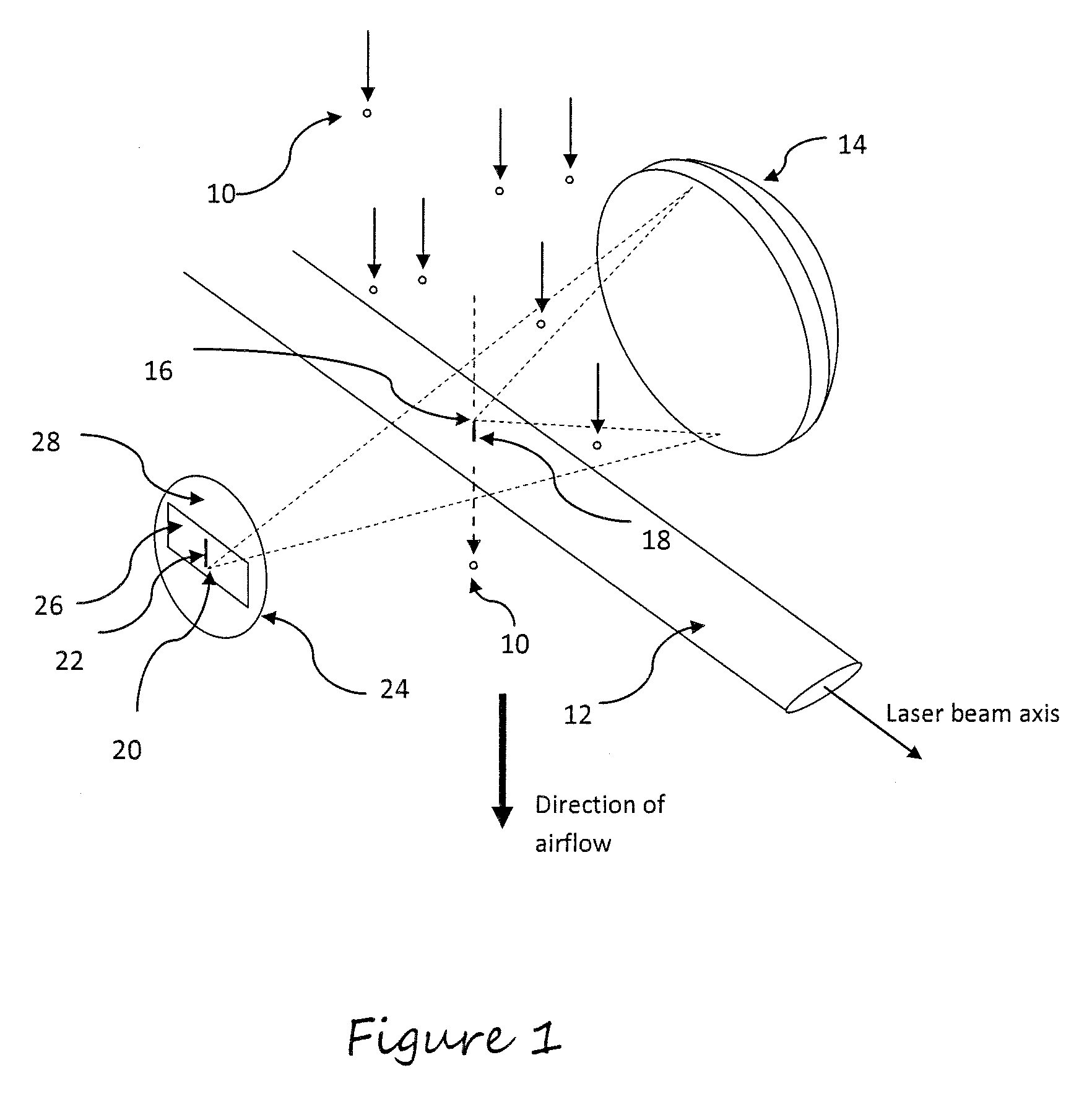
[0075]The preferred embodiment requires a flow of particles 10 carried in a moving airstream to pass through a laser beam 12, where the axis of the laser beam is orthogonal to the direction of the airflow, as in FIG. 1. The particles 10 are not constrained and may pass anywhere through the laser beam 12. It is well known that the size of a particle may be determined by measuring at some angle the intensity of light scattered by the particle as it passes through the beam. However, the non-uniform intensity profile of the beam (typically Gaussian) means that a particle passing through the edge of the beam will be illuminated with a lower intensity of light than an identically-sized particle passing through the centre of the beam. It will thus scatter less light and will be measured as smaller than the particle passing through the centre of the beam.

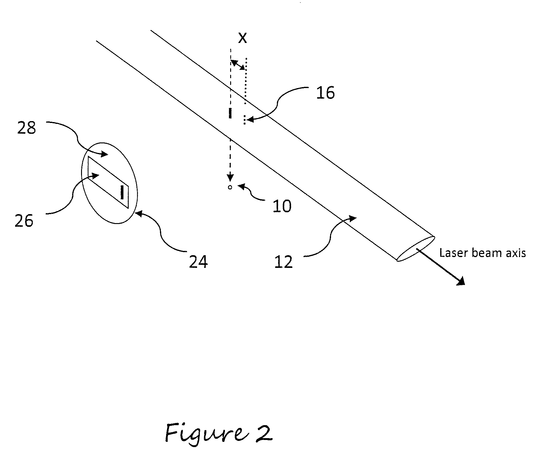
[0076]Because of this potential source of particles sizing error, it is necessary to optically define a small sensing zone within the cent...


PUM

PropertyMeasurementUnit
diameteraaaaaaaaaa
angleaaaaaaaaaa
diameteraaaaaaaaaa

Abstract

An apparatus for the detection of a fluid-borne particle (10) in an optically defined particle sensing zone, the apparatus comprising: i) a scattering chamber (40); ii) a means for providing a sample of fluid (34), containing the fluid-borne particle, in the form of a flow through the optically defined particle sensing zone; iii) A means for generating a beam of radiation (12) through the optically defined particle sensing zone; iv) a single reflector or refractor (14) means having a primary focus (16) within the optically defined particle sensing zone and a secondary focus (20) located outside the beam of radiation; v) a detector means comprising a first photosensitive detection area (26) a second photosensitive detection area (29); vi) a means for deriving area from the radiation detected by the first photosensitive detection area and second photosensitive detection area of the detection means wherein the single reflector or refractor means is adapted to direct radiation scattered from the fluid borne particle passing through the beam of radiation within the optically defined particle sensing zone to the detection means located at the secondary focus of the single reflector or refractor means and the optically sensing zone comprises a first and a second zone.

Description

FIELD OF THE INVENTION[0001]The present invention relates to a low cost apparatus and method for the detection of a fluid-borne particle. It is particularly applicable for the detection of a fluid-borne particle in an optically defined sensing zone.BACKGROUND OF THE INVENTION[0002]In many fields of environmental monitoring, workplace monitoring, pollution control, and occupational health monitoring, it is necessary to continuously measure the aerosol content of a local environment. Where real-time high-sensitivity measurements are desired, instruments are used that are capable of measuring the sizes of individual particles at high rates (typically thousands of particles per second) so that an accurate assessment of both the concentration of particles and their size distribution can be achieved.[0003]The instruments that are commonly used for this purpose are ‘optical particle counters’ (OPC). These use an intense light source (usually a laser) to illuminate a narrow column of sample...

Claims


Application Information

Patent Timeline
Patent Type & Authority Patents(United States)
IPC IPC(8): G01N21/51G01N21/47G01N15/14G01N15/02G01N1/22
CPCG01N15/0205G01N15/1434G01N21/51G01N21/47G01N2001/2223G01N2015/1486G01N2015/1493G01N21/53G01N2015/0238
Inventor KAYE, PAUL HENRYHIRST, EDWIN
Owner ALPHASENSE LTD
Why Eureka
Try Eureka