Microscope device

a microscope and lens technology, applied in the field of microscope devices, can solve the problems of inability to cope with the desire to acquire information on a deeper level, long scanning time, and inability to scan in the field of depth, and achieve the effect of long scanning time, and easy scanning of illumination rays

Active Publication Date: 2015-08-25
YOKOGAWA ELECTRIC CORP
View PDF24 Cites 8 Cited by
  • Summary
  • Abstract
  • Description
  • Claims
  • Application Information

AI Technical Summary

Benefits of technology

[0008]In Non-patent Document 2, it has been described that a structure made up of lenses relatively low in NA has advantageous effects as follows:
[0009]Further, in FIG. 7 of U.S. Pat. No. 5,973,828, there has been disclosed a scanning mechanism for scanning respective positions of focal points while keeping positional relation between two objective lenses. Still further, in Non-patent Document 1, and Non-patent Document 2, there has been disclosed a method for scanning while moving an object with the use of a stage, and so forth.[Patent Document 1] U.S. Pat. No. 5,973,828[Patent Document 2] U.S. Pat. No. 5,969,854[Patent Document 3] U.S. Pat. No. 6,423,956[Patent Document 4] German Patent No. 4326473[Non-patent Document 1]“Confocal microscope with large field and working distance”, Applied Optics, Vol. 38, No. 22, pp. 4870[Non-patent Document 2]“Dual axis confocal microscope for high resolution in vivo imaging”, Optics Letters, Vol. 28, No. 6, pp. 414SUMMARY OF THE INVENTION
[0010]However, it is considered that the mechanism for scanning the respective positions of focal points while keeping positional relation between the focal points of light rays passing through two objective lenses intersecting each other at an angle will be complex, and scanning will take time. Further, it is also considered that in the case of adopting the method for scanning while moving an object with the use of the stage, and so forth, very long scanning time will be required in practice. Further, with the use of the two objective lenses intersecting each other at an angle, light rays are irradiated from one side while the light rays are detected on the other side, so that an S / N ratio of a signal is enhanced, and observation on a deep part of a living organism is now possible.
[0011]However, it is still impossible to cope with a desire for acquiring information on a deeper part thereof.
[0012]The first to third inventions each have an object of providing a microscope device capable of easily scanning illumination rays, and suitable for observation on a deep part of a living organism.
[0013]Further, it is an object of the fourth invention to provide a microscope device capable of acquiring information on a part deeper than that in the case of a conventional microscope device, and suitable for observation on a deep part of a living organism.

Problems solved by technology

However, it is considered that the mechanism for scanning the respective positions of focal points while keeping positional relation between the focal points of light rays passing through two objective lenses intersecting each other at an angle will be complex, and scanning will take time.
Further, it is also considered that in the case of adopting the method for scanning while moving an object with the use of the stage, and so forth, very long scanning time will be required in practice.
However, it is still impossible to cope with a desire for acquiring information on a deeper part thereof.

Method used


Image

  • Microscope device
  • Microscope device
  • Microscope device

Examples


embodiment 1

[0123]A microscope device according to Embodiment 1 is described hereinafter with reference to FIGS. 1 to 3.

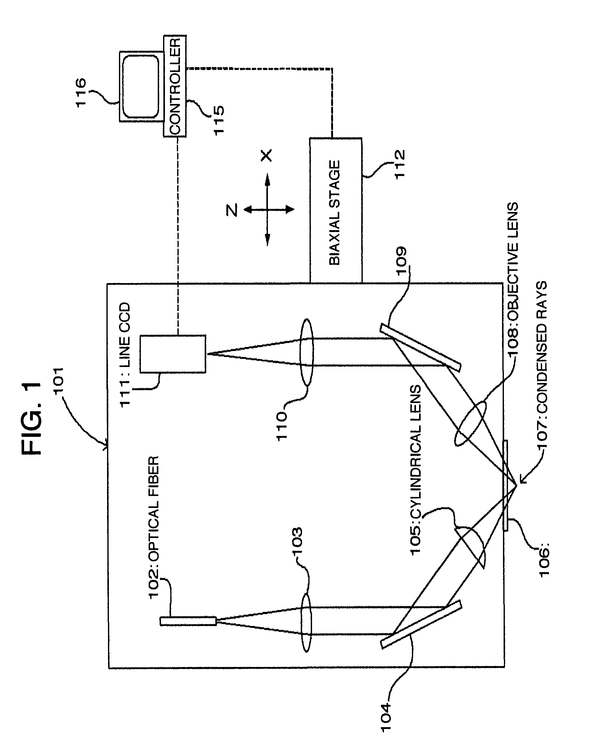
[0124]FIG. 1 is a block diagram showing a configuration of the microscope device according to Embodiment 1.

[0125]As shown in FIG. 1, an optical fiber 102 for guiding light rays from a light source (not shown) is disposed at an optical head 101 of the microscope device according to the present embodiment. In this case, near infrared rays for observation on a deep part of a living organism are preferable as the light rays from the light source, and the optical fiber 102 small in core diameter, such as a single-mode fiber, is preferable. A collimator lens 103 is provided in front of the optical fiber 102.

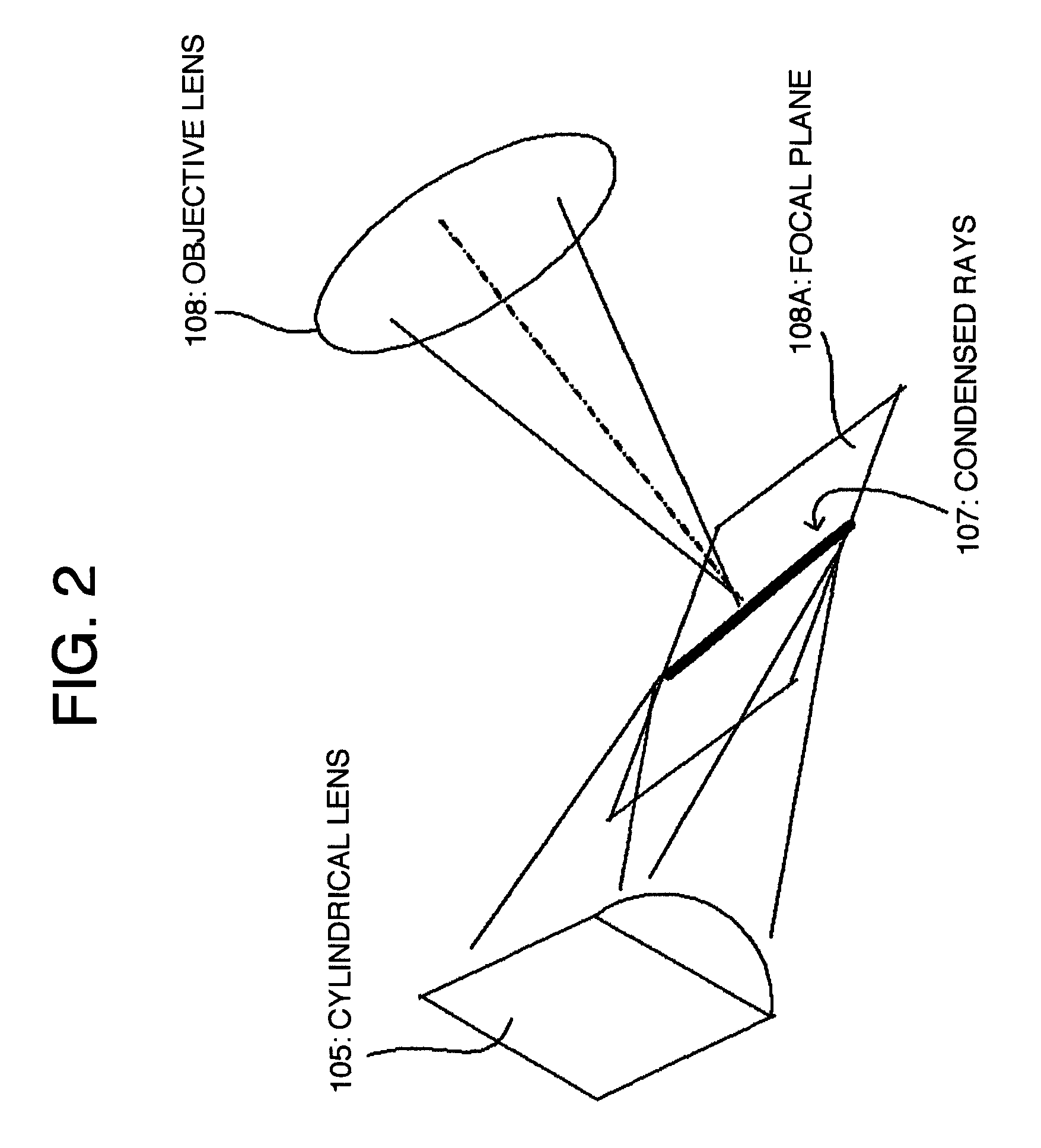
[0126]Further, the optical head 101 comprises a reflecting mirror 104, a cylindrical lens 105, an aperture window 106, an objective lens 108, a mirror 109, and an imaging lens 110, which are all disposed along an optical path.

[0127]The cylindrical lens 105 comprises a circular cy...

embodiment 2

[0146]A microscope device according to Embodiment 2 is described hereinafter with reference to FIGS. 4 to 6.

[0147]FIG. 4 is a block diagram showing a configuration of the microscope device according to Embodiment 2.

[0148]As shown in FIG. 4, an optical head 101A of the microscope device according to the present embodiment comprises an optical fiber 121 for guiding light rays from a light source (not shown), a collimator lens 122, a cylindrical lens 123, a slit 124 provided at a point of condensed light rays from the cylindrical lens 123, an imaging lens 125, reflecting mirrors 126, 127, and an objective lens 128, which are all disposed along an optical path of an illumination optical system.

[0149]Further, an objective lens 130 is disposed such that a focal point 129 of the objective lens 130, on a side thereof, adjacent to an object, will coincide with that of the objective lens 128. An angle between optical axes of the two objective lenses is 90°. For those objective lenses 128, 130...

embodiment 3

[0181]There is described hereinafter the microscope device according to Embodiment 3 with reference to FIGS. 7 to 9.

[0182]FIG. 7 is a block diagram showing a configuration of the microscope device according to Embodiment 3.

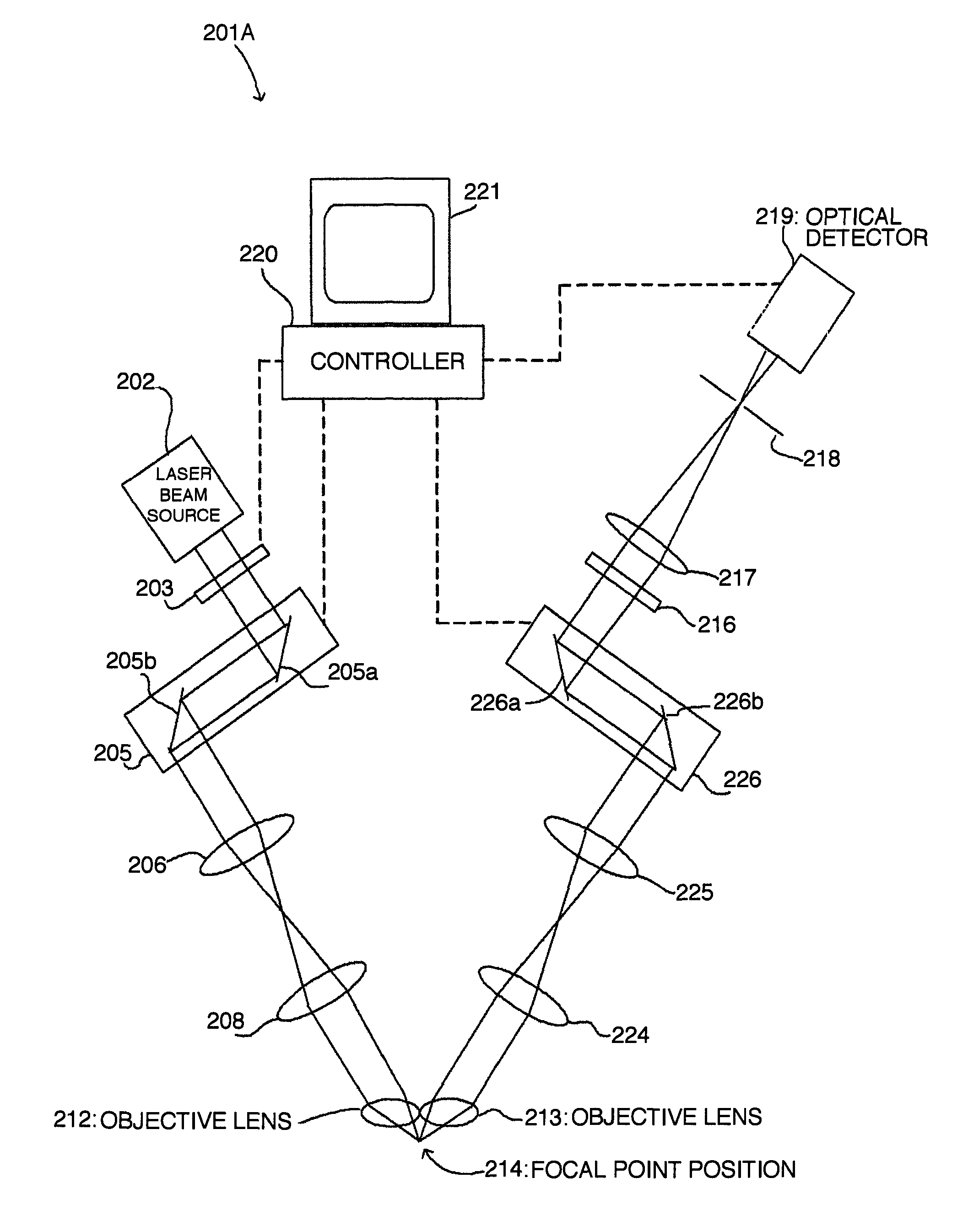
[0183]A microscope device 201 according to the present embodiment has a near infrared radiation (NIR) laser beam source 202, and an electric shutter 203 is disposed in front of the NIR laser beam source 202. Further, the microscope device 201 comprises a dichroic mirror 204 for altering orientation of a laser beam, and a scanning optical unit 205 for scanning the laser beam.

[0184]The dichroic mirror 204 has characteristics of reflecting the wavelength of the laser beam, and allowing fluorescent rays excited by the laser beam to transmit therethrough. The scanning optical unit 205 comprises a variable mirror 205a rotatable around a rotation axis, and a variable mirror 205b rotatable around an axis substantially orthogonal to the rotation axis of the variable mirror...


PUM


Abstract

With a microscope device according to the invention, it is possible to acquire information on a deeper part of a living organism than that in the case of a conventional microscope device. The microscope device according to a first invention comprises an illumination optical system for irradiating an object with illumination rays in a line-like form, a detection optical system for receiving light rays generated by the illumination rays. The second invention relates to a microscope device wherein an objective lens of an illumination optical system, and an objective lens of a detection optical system are at respective positions. The third invention relates to a microscope device wherein a separation filter is structured such that a laser beam can pass through only a part (a region) thereof. The fourth invention relates to a microscope device wherein illumination rays having coherence are separated into two portions.

Description

FIELD OF THE INVENTION[0001]The present invention includes first to fourth inventions, the first invention relating to a microscope device comprising an illumination optical system for irradiating an object with illumination rays in a line-like form, a detection optical system for receiving light rays generated by the illumination rays in the line-like form to thereby form an image on a detector, and scanning means for scanning the illumination rays in the line-like form, wherein information on an image on a flat plane, obtained by scanning the illumination rays in the line-like form by use of the scanning means, is acquired on the basis of a signal from a detector.[0002]The second invention relates to a microscope device wherein an objective lens of an illumination optical system for irradiating an object with illumination rays, and an objective lens of a detection optical system for detecting feedback light rays based on the illumination rays are at respective positions where resp...

Claims


Application Information

Patent Timeline
Patent Type & Authority Patents(United States)
IPC IPC(8): G02B21/06G02B21/16G02B21/00G02B21/14
CPCG02B21/16G02B21/008G02B21/0076G02B21/06G02B21/14
Inventor SANGU, HIROYUKI
Owner YOKOGAWA ELECTRIC CORP
Why Eureka
Try Eureka