Wearable antenna having a microstrip feed line disposed on a flexible fabric and including periodic apertures in a ground plane

a microstrip and feed line technology, applied in the direction of antennas, antenna adaptation in movable bodies, waveguides, etc., can solve the problems of fragile use and difficult realization of narrow conductors, and achieve the effects of low loss, low resistance and high precision

Active Publication Date: 2015-08-25
BAE SYSTEMS PLC
View PDF19 Cites 2 Cited by
  • Summary
  • Abstract
  • Description
  • Claims
  • Application Information

AI Technical Summary

Benefits of technology

[0014]It has been found possible to construct an embodiment of the invention on materials no thicker than 0.5 mm and even on cotton having a thickness of only 0.3 mm. A conventional transmission line feed for an antenna would normally present considerable problems at these separations between the ground plane and the line conductor, particularly in terms of fragility, to achieve appropriate impedance. The perforated ground plane allows a wider line conductor to be used to achieve impedance in a convenient range, preferably around 50 ohms but optionally in the range from 35 ohms to 65 ohms, and this in turn means lower resistance and therefore lower loss.
[0015]Rather than printing or otherwise providing the components o

Problems solved by technology

Such narrow conductors are very diffic

Method used


Image

  • Wearable antenna having a microstrip feed line disposed on a flexible fabric and including periodic apertures in a ground plane
  • Wearable antenna having a microstrip feed line disposed on a flexible fabric and including periodic apertures in a ground plane
  • Wearable antenna having a microstrip feed line disposed on a flexible fabric and including periodic apertures in a ground plane

Examples


Embodiment Construction

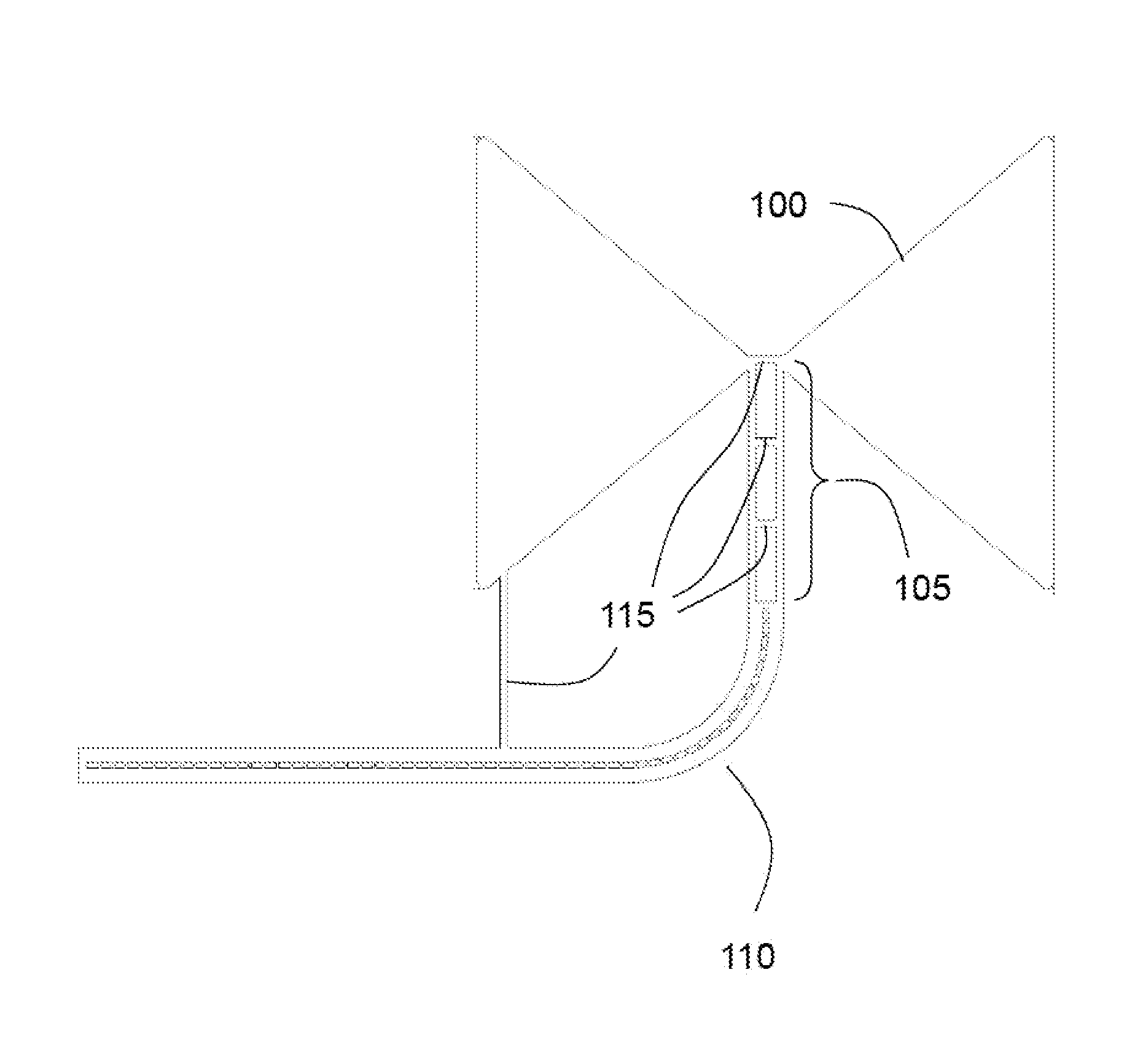
[0028]Referring to FIG. 1, in practice, a bowtie antenna 100 with a ground plane for its feed structure 105, 110 can be fabricated from a sheet of conductive material, prior to mounting on a wearable fabric. The antenna 100 as shown will be mounted on the inside of the wearable fabric and comprises a low-band bow-tie antenna 100 connected to the ground plane 110 of a transmission line feed via the ground plane 105 of a Marchand balun. Thus in this embodiment the antenna and its feed structure share a continuous ground plane in that the ground plane of each is constructed from the same, continuous piece of material.

[0029]A suitable balun is further discussed below with reference to FIGS. 5 and 6.

[0030]The antenna 100 is of known type, being a bow-tie dipole.

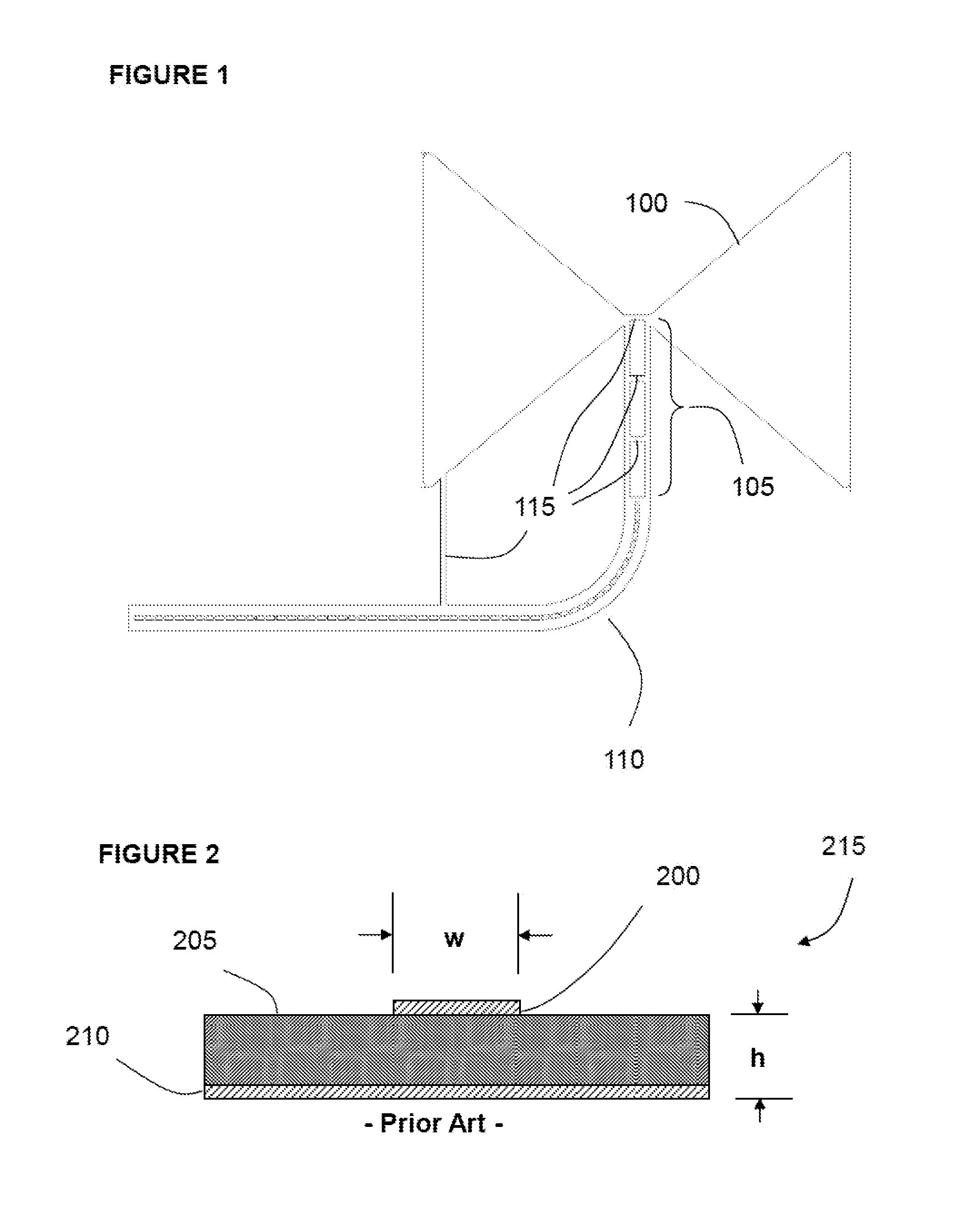
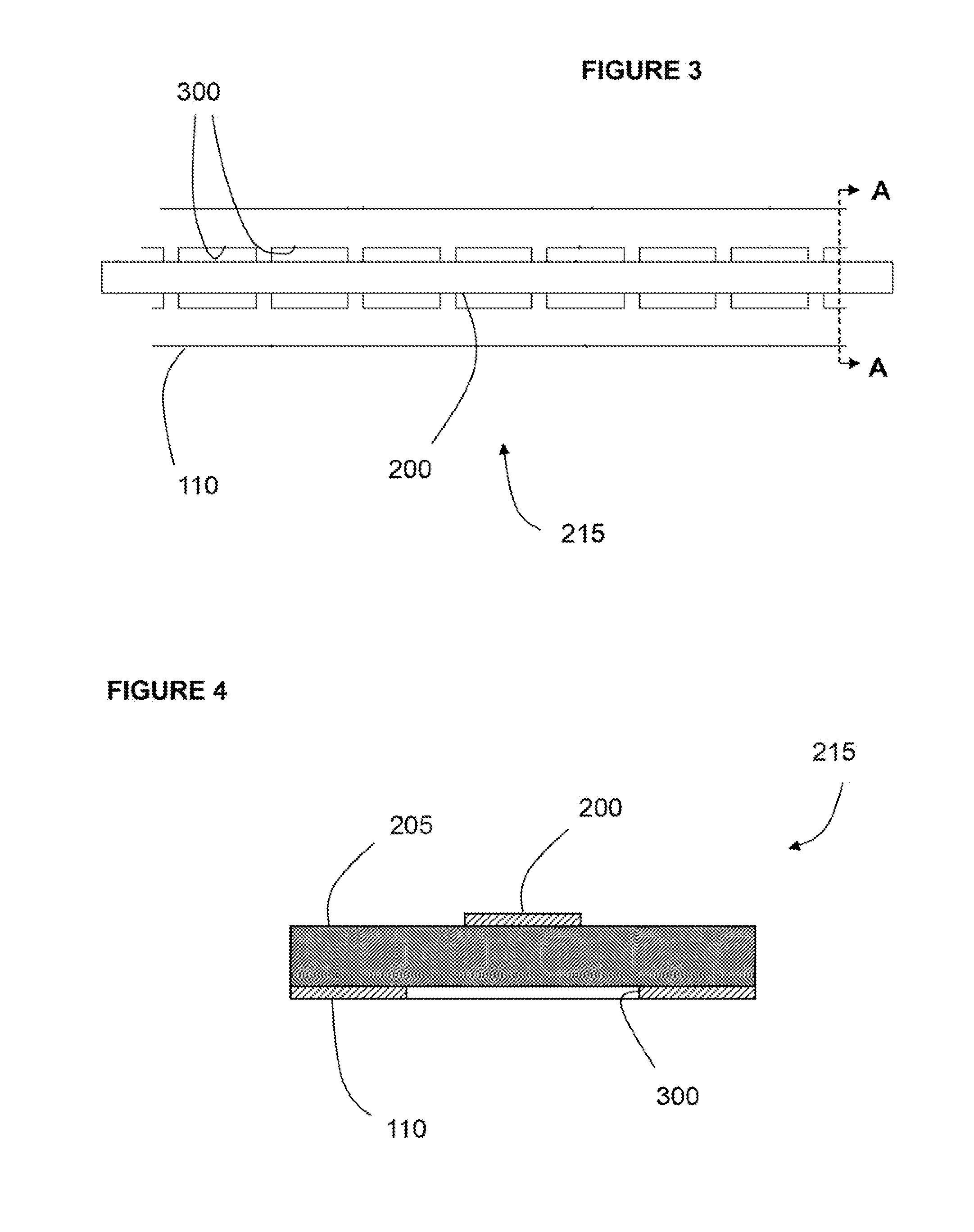
[0031]The ground plane of the transmission line feed 110 is perforated and provides part of a 50 ohm microstrip line which is further described below with particular reference to FIGS. 2 to 4. To obtain vertical polarisation, the ...


PUM


Abstract

A feed structure for a wearable antenna incorporates a microstrip transmission line designed for mounting on opposite sides of a fabric. The transmission line has a perforated ground plane which reduces capacitance and offers an appropriate impedance, even when the fabric is thin, and allows the use of a relatively robust line conductor having a width of 3 mm or 5 mm or more. The ground plane can be extended to provide the ground plane of a balun and the material of that ground plane can in turn be extended to provide the wearable antenna.

Description

CROSS-REFERENCE TO RELATED APPLICATIONS[0001]This application is a U.S. National Stage application under 35 USC §371 of PCT / GB2011 / 000994 filed 29 Jun. 2011, which claims priority under the Paris Convention to European Patent Application 10275069.2 filed 30 Jun. 2010, and British Patent Application 1010988.2 filed 30 Jun. 2010, the entire contents of both applications being incorporated herein by reference.BACKGROUND[0002]The present invention relates to a feed structure for an antenna. Embodiments of the invention find particular application in flexible feed structures for radio antennas, such as those which can be incorporated into clothing.[0003]Wearable antennas have been developed for use in variety of communications applications. The construction of an antenna using flexible materials has been investigated and can give a relatively discreet result which does not hinder the wearer's movements.[0004]There are several challenges in developing a wearable antenna which can for exam...

Claims


Application Information

Patent Timeline
IPC IPC(8): H01P3/02H01P3/08H01Q9/28H01Q1/38H01Q1/27
CPCH01P3/026H01P3/081H01Q1/273H01Q1/38H01Q9/285
Inventor HENDERSON, ROBERT IANMATTHEWS, JAMES CHRISTOPHER GORDON
Owner BAE SYSTEMS PLC
Why Eureka
Try Eureka