
Synthetic amorphous silica powder and method for producing same

a technology of synthetic amorphous silica and silica powder, which is applied in the direction of synthetic resin layered products, natural mineral layered products, energy-based chemical/physical/physical-chemical processes, etc., can solve the problems that the purity of obtained raw materials has not been fully satisfied, and achieve the effect of reducing the amount of gas bubble generation or the degree of expansion

Active Publication Date: 2015-09-01
MITSUBISHI MATERIALS CORP
View PDF18 Cites 11 Cited by
  • Summary
  • Abstract
  • Description
  • Claims
  • Application Information

AI Technical Summary

Benefits of technology

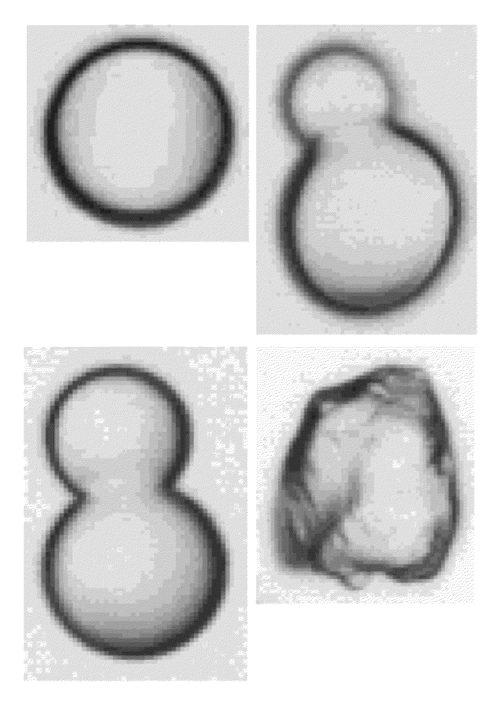
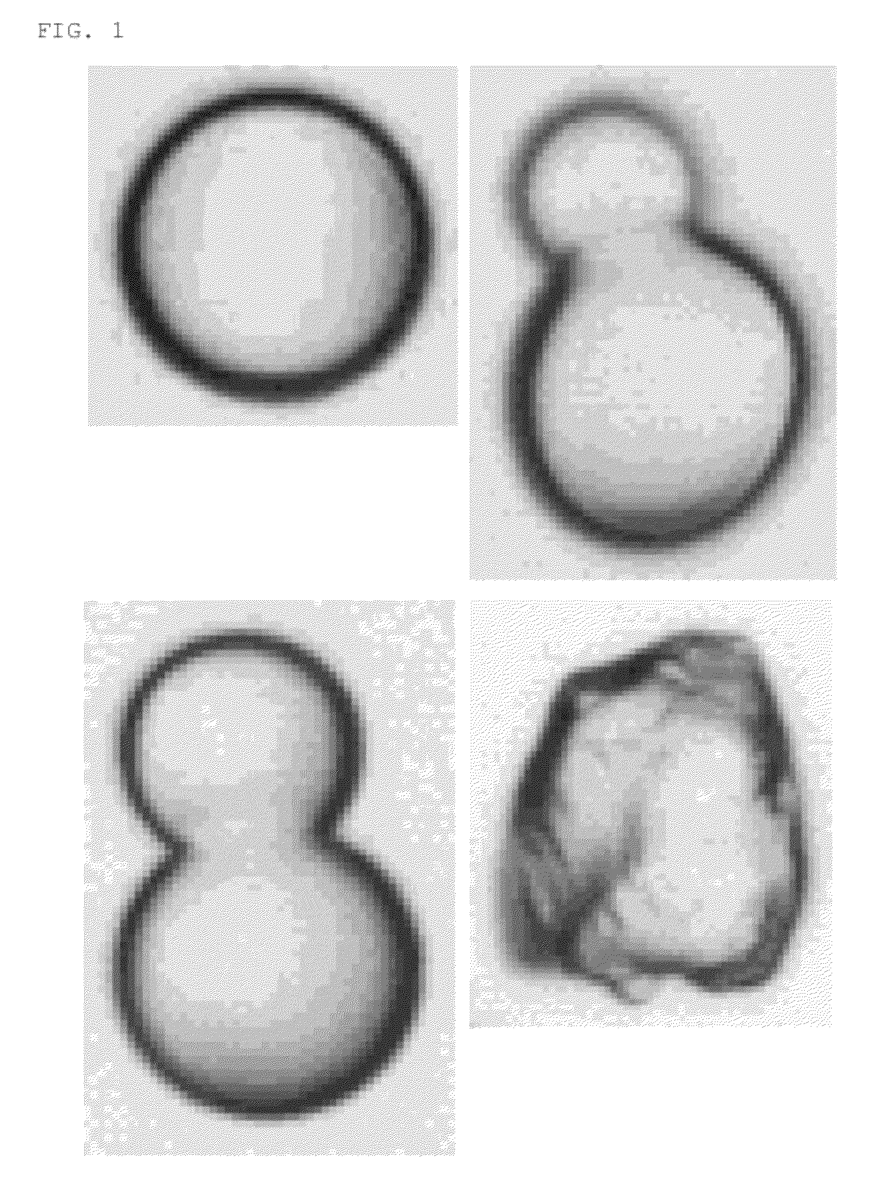
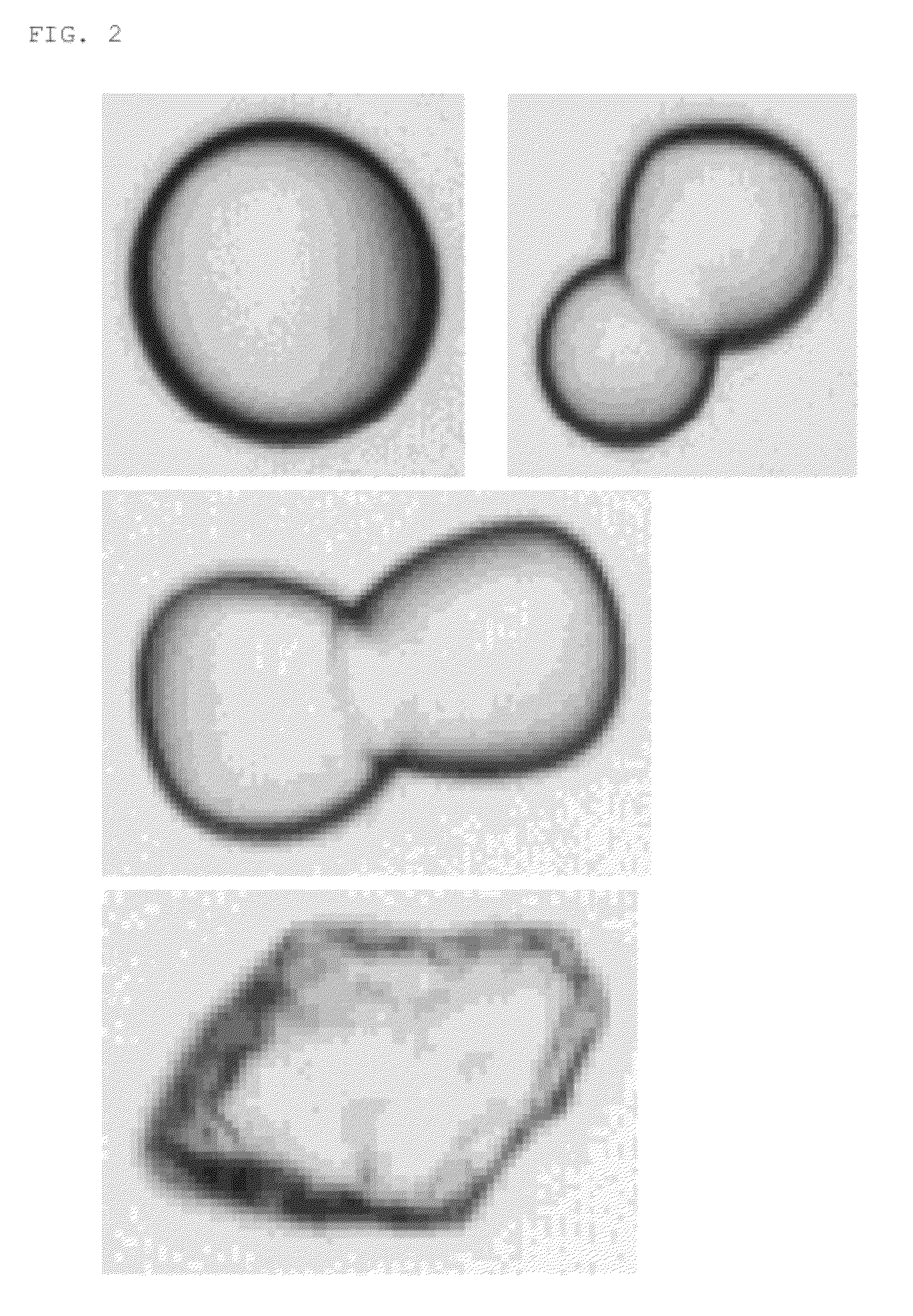
[0062]The synthetic amorphous silica powder according to the first aspect of the present invention is a synthetic amorphous silica powder obtained by applying a spheroidizing treatment to a granulated silica powder, and by subsequently cleaning and drying it so that the synthetic amorphous silica powder has an average particle diameter D50 of 10 to 2,000 μm;
[0064]a quotient of 1.00 to 1.35 obtained by dividing a BET specific surface area of the powder by a theoretical specific surface area calculated from the average particle diameter
[0070]Thus, by using this synthetic amorphous silica powder to manufacture a synthetic silica glass product, gas components adsorbed to surfaces of particles of a raw powder are less in amount and gas components inside the powder particles are also less in amount, thereby enabling to reduce an amount of generation or degree of expansion of gas bubbles.
[0071]The synthetic amorphous silica powder according to the second aspect of the present invention is obtained by applying the spheroidizing treatment to the granulated silica powder after firing it; wherein the synthetic amorphous silica powder satisfies one or both of the conditions that it has a carbon concentration less than 2 ppm and that it has a chlorine concentration less than 2 ppm. Thus, by using this synthetic amorphous silica powder to manufacture a synthetic silica glass product, gas components adsorbed to surfaces of particles of a raw powder are less in amount and gas components inside the powder particles are also less in amount, thereby enabling to reduce an amount of generation or degree of expansion of gas bubbles. Particularly, in case of this synthetic amorphous silica powder, firing is conducted before applying the spheroidizing treatment to the powder, so that gas components to be adsorbed to surfaces of powder particles and gas components inside the particles are extremely decreased in amount, thereby further enhancing an effect for reducing an amount of generation or degree of expansion of gas bubbles in the above synthetic silica glass product.
[0072]In case of the synthetic amorphous silica powder according to the fifth aspect of the present invention, the granulated silica powder is a silica powder obtained by: using a fumed silica to produce a siliceous gel; drying the siliceous gel to turn it into a dry powder; pulverizing particles of the dry powder; and then classifying the pulverizedly obtained particles; thereby achieving that the synthetic amorphous silica powder has a carbon concentration less than 2 ppm and a chlorine concentration less than 2 ppm.
[0073]In case of this synthetic amorphous silica powder, the granulated silica powder is further restricted in carbon concentration and chlorine concentration by using fumed silica as a silica powder as a raw powder, as compared to a granulated silica powder which uses, as a raw powder, a silica powder obtained by reacting a chlorine-based silicon compound in a liquid or a silica powder obtained from an organic silicon compound such as tetramethoxysilane; thereby further enhancing an effect for reducing an amount of generation or degree of expansion of gas bubbles in the synthetic silica glass product.

Problems solved by technology

However, the natural quartz, quartz sand, or the like contains various metal impurities which are not completely removed therefrom even by the purification treatment, so that the thus obtained raw material has not been fully satisfied in purity.

Method used


Image

  • Synthetic amorphous silica powder and method for producing same
  • Synthetic amorphous silica powder and method for producing same
  • Synthetic amorphous silica powder and method for producing same

Examples


example 1

[0143]Firstly, ultrapure water was prepared in an amount equivalent to 55.6 mols, per 1 mol of silicon tetrachloride. This ultrapure water was brought into a vessel, and then the carbon tetrachloride was added thereinto, with stirring while keeping the temperature at 25° C. in an atmosphere of nitrogen, thereby hydrolyzing the silicon tetrachloride. After addition of the silicon tetrachloride, stirring was continued for 2 hours, thereby producing a siliceous gel. At this time, the stirring speed was set to be 100 rpm. Next, the siliceous gel was transferred into a container for drying which was brought into a drier, and the siliceous gel was dried for 24 hours at a temperature of 200° C. while flowing nitrogen through within the drier at a flow rate of 10 L / min, thereby obtaining a dry powder. This dry powder was then taken out of the drier, and pulverized by a roll crusher. At this time, pulverizing was conducted by adjusting a roll gap to 0.2 mm and a roll revolution speed to 40 r...

example 2

[0147]Firstly, 2 mols of ultrapure water and 2 mols of ethanol were prepared per 1 mol of tetramethoxysilane. The prepared ultrapure water and ethanol were charged into a vessel, and then the tetramethoxysilane was added thereinto, with stirring while keeping the temperature at 60° C. in an atmosphere of nitrogen, thereby hydrolyzing the tetramethoxysilane. After addition of the tetramethoxysilane, stirring was continued for 60 minutes, and 30 mols of ultrapure water was further added thereinto per 1 mol of tetramethoxysilane, followed by continued stirring for 5 hours, thereby producing a siliceous gel. At this time, the stirring speed was set to be 100 rpm. Next, the siliceous gel was transferred into a container for drying which was brought into a drier, and the siliceous gel was dried for 48 hours at a temperature of 200° C. while flowing nitrogen through within the drier at a flow rate of 20 L / min, thereby obtaining a dry powder. This dry powder was then taken out of the drier,...

example 3

[0151]Firstly, 10 mols of ultrapure water was prepared per 1 mol of fumed silica having an average particle diameter D50 of 0.030 μm and a specific surface area of 50 m2 / g. The prepared ultrapure water was charged into a vessel, and then the fumed silica was added thereinto, with stirring while keeping the temperature at 25° C. in an atmosphere of nitrogen. After addition of the fumed silica, stirring was continued for 3 hours, thereby producing a siliceous gel. At this time, the stirring speed was set to be 30 rpm. Next, the siliceous gel was transferred into a container for drying which was brought into a drier, and the siliceous gel was dried for 12 hours at a temperature of 300° C. while flowing nitrogen through within the drier at a flow rate of 10 L / min, thereby obtaining a dry powder. This dry powder was then taken out of the drier, and pulverized by a roll crusher. At this time, pulverizing was conducted by adjusting a roll gap to 0.5 mm and a roll revolution speed to 100 rp...


PUM

PropertyMeasurementUnit
frequencyaaaaaaaaaa
temperatureaaaaaaaaaa

Abstract

The synthetic amorphous silica powder of the present invention is characterized in that it comprises a synthetic amorphous silica powder obtained by applying a spheroidizing treatment to a silica powder, and by subsequently cleaning and drying it so that the synthetic amorphous silica powder has an average particle diameter D50 of 10 to 2,000 μm; wherein the synthetic amorphous silica powder has: a quotient of 1.00 to 1.35 obtained by dividing a BET specific surface area of the powder by a theoretical specific surface area calculated from the average particle diameter D50; a real density of 2.10 to 2.20 g / cm3; an intra-particulate porosity of 0 to 0.05; a circularity of 0.75 to 1.00; and an unmolten ratio of 0.00 to 0.25.

Description

CROSS REFERENCE TO RELATED APPLICATIONS[0001]This application is related to two co-pending applications: “SYNTHETIC AMORPHOUS SILICA POWDER AND METHOD FOR PRODUCING SAME” filed even date herewith in the name of Toshiaki Ueda as a national phase entry of PCT / JP2010 / 073499 filed Dec. 27, 2010 and “SYNTHETIC AMORPHOUS SILICA POWDER AND METHOD FOR PRODUCING SAME” filed even date herewith in the name of Toshiaki Ueda as a national phase entry of PCT / JP2010 / 073287 filed Dec. 24, 2010; which applications are assigned to the assignee of the present application and both incorporated by reference herein.TECHNICAL FIELD[0002]The present invention relates to a synthetic amorphous silica powder with high purity and a method for producing the same, which silica powder is suitable as a raw material for manufacturing a synthetic silica glass product such as a piping, crucible, or the like to be used in a high temperature and reduced pressure environment in a semiconductor industry and the like.BACK...

Claims


Application Information

Patent Timeline
Patent Type & Authority Patents(United States)
IPC IPC(8): C01B33/12C03C3/06C01B33/14C01B33/18
CPCC01B33/181C01B33/14C03C3/06C01P2004/03C01P2004/32C01P2004/54C01P2004/61C01P2006/12Y10T428/2982C01B33/18B01J6/00B01J19/08B22F1/00C01B33/158C03B19/1065C03B19/1095C03B2201/02C03C23/0075
Inventor UEDA, TOSHIAKI
Owner MITSUBISHI MATERIALS CORP
Learn More