Self-healing composites
a self-healing composite and composite material technology, applied in the field of light-weight self-healing composites, can solve the problems of heavy and difficult to form anti-ballistic steel, brittle ceramics in general and tend to degrade, and all current anti-ballistic materials are expensive and in most cases heavy
- Summary
- Abstract
- Description
- Claims
- Application Information
AI Technical Summary
Benefits of technology
Problems solved by technology
Method used
Image
Examples
example 1
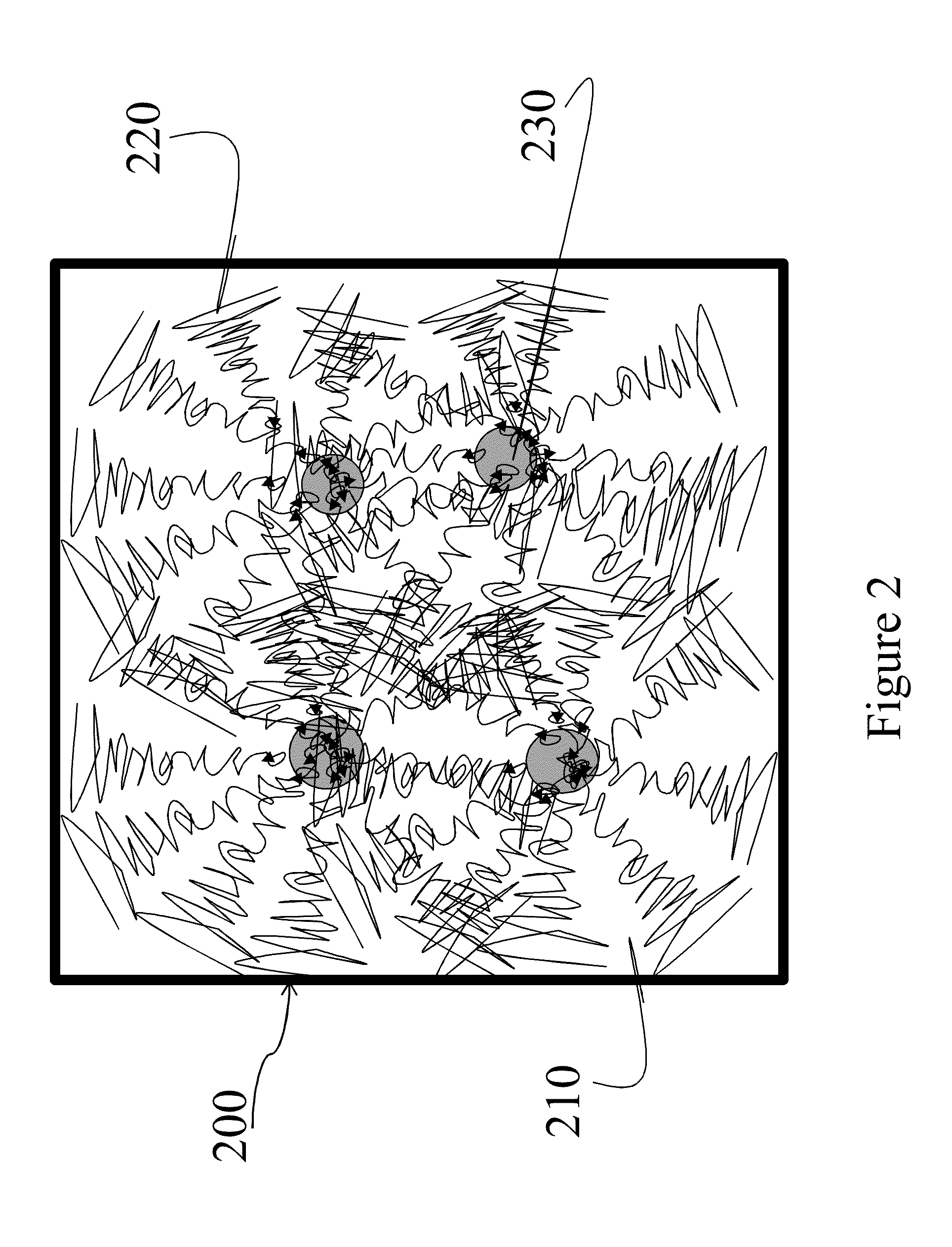
[0081]In a two-step process, component A, B, C, and / or D in total of about three pounds were first pre-blended in dry in a ratio as shown in Table 1 in a high intensity Hensehel mixer for about 40 minutes to ensure a well dispersion. The resulting mixture was then compounded using a C. W. Brabender (Model PL 2000) twin-screw extruder (counter-rotating) at a temperature profile of 200° C., 215° C., 220° C., and 220° C., to ensure even dispersion of the nanocomposite system as schematically shown in FIG. 4. The resulting extrudates exiting from a die of the extruder at temperature of 228° C. from the above two-step process were then air-cooled and pelletized into uniform pellets (3 mm in diameter and 5 mm in length) for further characterization and downstream process. All the samples exhibited good processability in formation of pellets.[0082]Component A, the base resin is selected from one of the following HMWHDPE sources: (1) The Regrind material is taken from the waste stream, cont...
example 2
[0087]The resulting compounded pellets made from the example 1 were then fed and extruded through a C.W. Brabender twin-screw extruder (counter rotating) with a die opening of about ½ inch. The extrudate was then guided into a preheated mold of 6 inch by 6-inch by 3-inch in an alternating crisscross pattern in multiple layers until the mold filled up with the extrudate. The mold was then covered with a square cap and transferred to a Carver compression molding machine. The Carver compression molding machine was controlled at the temperature of 125° C., slightly below the melting of the polymer resin, for both platens. The compression molding machine was maintained at over 1,380 pounds per square inch for about 1 hour. The pressure was then gradually reduced to zero pounds per inch while the platens were gradually cooled down to room temperature. The sample panels of 6-inch by 6-inch of about 1 inch thick were then removed from the mold for testing their ballistic energy dampening pr...
example 3
Static Mechanical Properties at 25° C.
[0088]The resulting compounded pellets made from example 1 and a comparative sample, Marle™ K605 HMWHDPE pellets from Chevron Phillips Chemical Company LP (as Comparative A), were then fed into an injection molding machine (Mini-Jector) at a temperature profile of 204° C., 221° C., and 221° C., respectively. The mold with captivity for tensile testing was preheated in an oven at about 150° C. The resulting samples were then tested for static mechanical properties including tensile modulus and tensile strength at break. The testing results were summarized in Table 2.
[0089]The standard method for determining tensile properties of plastics (ASTM D 638) was used to study the Young's modulus and tensile strength at break of the specimens prepared from the injection molding experiments, using a Com-Ten universal testing machine. The experiment was carried out by hanging a dog-bone shape specimen bar between two metal grips while applying a constant st...
PUM
| Property | Measurement | Unit |
|---|---|---|
| Temperature | aaaaa | aaaaa |
| Temperature | aaaaa | aaaaa |
| Fraction | aaaaa | aaaaa |
Abstract
Description
Claims
Application Information
 - R&D
- Intellectual Property
- Life Sciences
- Materials
- Tech Scout
- Unparalleled Data Quality
- Higher Quality Content
- 60% Fewer Hallucinations
Browse by: Latest US Patents, China's latest patents, Technical Efficacy Thesaurus, Application Domain, Technology Topic, Popular Technical Reports.
© 2025 PatSnap. All rights reserved.Legal|Privacy policy|Modern Slavery Act Transparency Statement|Sitemap|About US| Contact US: help@patsnap.com


