Total ankle replacement

Active Publication Date: 2015-09-15
ZOYA
View PDF60 Cites 6 Cited by
  • Summary
  • Abstract
  • Description
  • Claims
  • Application Information

AI Technical Summary

Benefits of technology

[0007]A conventional ankle prosthesis includes a tibial component and a talocalcaneal component, which have bearing surfaces adjacent to one another that are nearly congruent and cylindrically curved, in a longitudinal direction, parallel to the length of the foot, while the wear surfaces are straight in a lateral direction, across the width of the foot. Lateral movement between the tibial and talus components is limited by flanges extending from one of the components past the wear surface of the other component. Axial rotation may be provided through the use of plates turning against one another. While flexure within the prosthesis in the plantar and dorsal directions is permitted by the curvature of the bearing surfaces, flexure in the inversion and eversion directions is prevented by the shape of the wear surfaces, which are straight in the lateral direction.
[0008]Conventional ankle replacement provides the patient with foot movement allowing a nearly normal gait, following recovery. While the patient can walk and perform low-impact exercises, he is cautioned against performing high-impact exercises, such as step aerobics and the use of an inclined treadmill or stairstep machine. The effective

Problems solved by technology

The effective life of the prosthesis is dependent on how it is used after recovery, with problems occurring particularly due to loosening of the components from the bone surfaces to which they are attached, requiring surgical correction, possibly with ankle fusion.
While such problems are associated with limitations in the bone stock available for the attachment of the prosthetic components, it is known that weakening of bone within the talus results in part from t

Method used


Image

  • Total ankle replacement
  • Total ankle replacement
  • Total ankle replacement

Examples


first embodiment

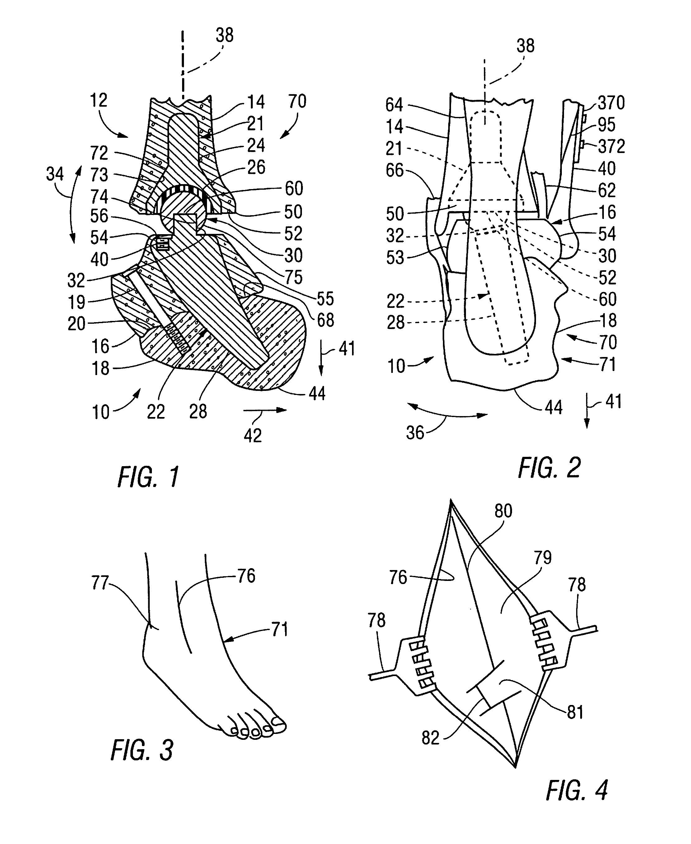
[0053]In accordance with the invention, both the socket 26 and the head 30 have spherical contact surfaces. The overall configuration of the construct 70 provides for planter / dorsal flexure in the directions of arrow 34, for flexure in the inversion / eversion directions of arrows 36, for axial rotation about axis 38 and for varus / valgus motion to occur in manners closely simulating normal anatomical ankle movement. The ligaments and soft tissue of the ankle, which remain intact during the installation of the prosthesis 12, freedom of movement and stability at the anatomical level. While subtalar movement has been prevented by fusing the talus 16 with the calcaneus 18, such movement is simulated by the movements available between the head 30 and the socket 26.

[0054]In accordance with a first embodiment of the invention, both the

[0055]In accordance with a preferred version of the invention, several versions of the head 30 are provided as a kit, with variations among the versions occurr...

second embodiment

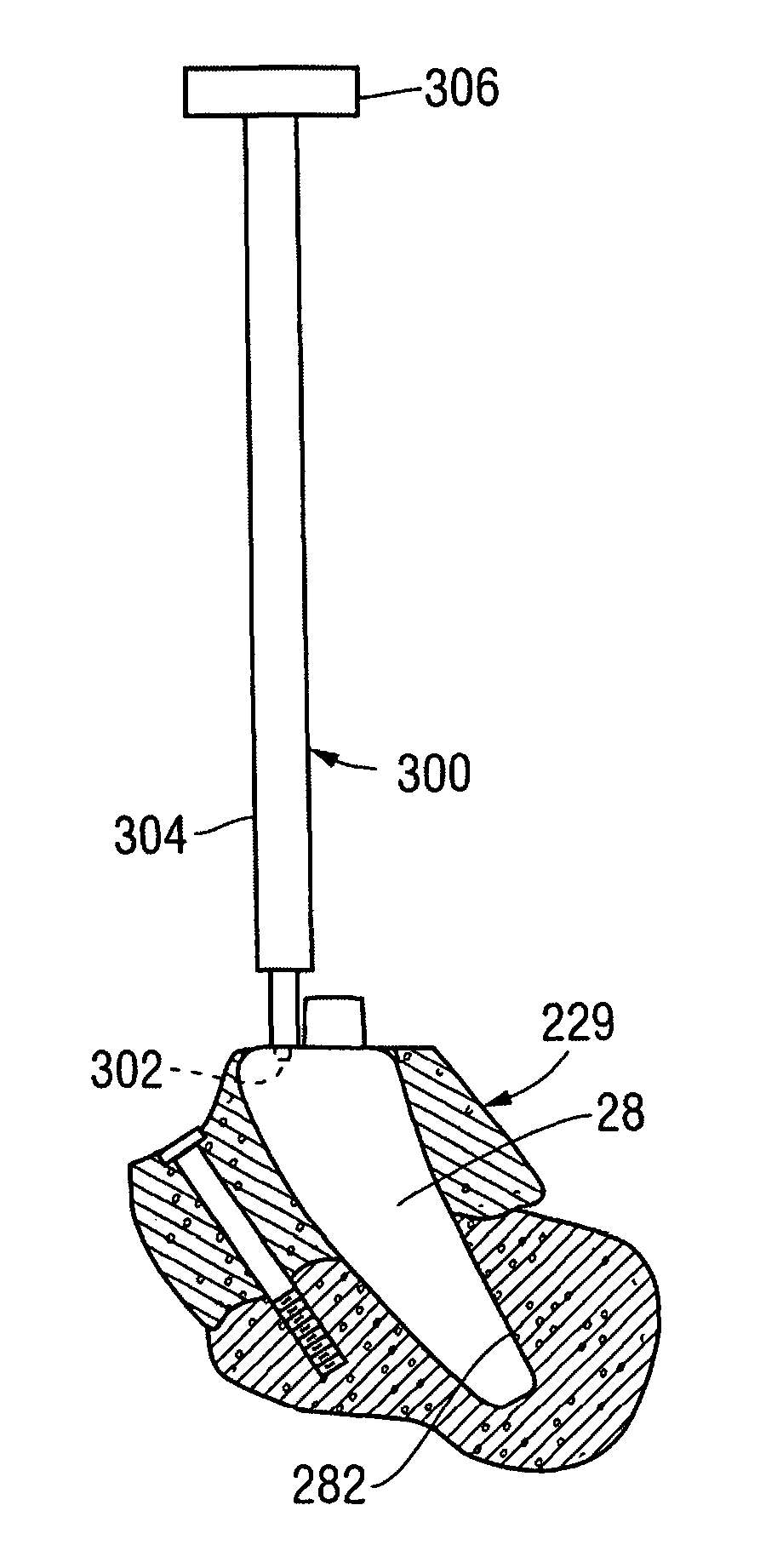
[0079]In accordance with the invention, mating features are provided within an ankle replacement prosthesis for limiting inversion / eversion rotation while providing for dorsal / plantar rotation. For example, FIGS. 23 and 24 show an ankle replacement prosthesis 400, built in accordance with a first alternative embodiment of the invention to include means for limiting inversion / eversion rotation, in the directions of arrow 402, to a level much less than a permitted level of dorsal / plantar rotation, in the directions of arrow 404. FIG. 23 is a medial view of the prosthesis 400, while FIG. 24 is a partly sectional posterior view thereof. The ankle replacement prosthesis 400 includes a talocalcaneal component 406 having a stem 408 that extends to the weight bearing portion 246 of the calcaneus 229 within the talocalcaneal compound 229 (all shown in FIG. 14). The ankle replacement prosthesis additionally includes a tibial component 409. The talocalcaneal component 406 additionally includes...


PUM


Abstract

An ankle replacement prosthesis includes a tibial component, attached within a cavity formed in the tibia, and a talocalcaneal component, attached within a slot formed within a talocalcaneal compound, previously formed by fusing the talus and the calcaneus. Preferably, the talocalcaneal component includes a neck, to which a head, having a contact surface engaging a contact surface within the tibial component, is adjustably attached. These contact surfaces may both be spherical, with the contact surface of the talocalcaneal component being formed as a ball fitting within a socket formed by the contact surface of the tibial component, or these contact surfaces may include mating feature that limit inversion/eversion rotation of the foot, while providing for dorsal/plantar rotation thereof.

Description

RELATED APPLICATIONS[0001]Not ApplicableFEDERALLY SPONSORED RESEARCH OR DEVELOPMENT[0002]Not ApplicableBACKGROUND OF THE INVENTION[0003]1. Field of the Invention[0004]This invention relates to a method and a prosthesis for total ankle replacement.[0005]2. Summary of the Background Information[0006]A surgeon begins a conventional ankle replacement process by making an incision in front of the ankle. Then, portions of the tibia and talus forming the damaged joint surfaces are removed through the incision and the surfaces of the tibia and talus are shaped to accept and hold the mating surfaces of the prosthesis, which is then inserted through the incision for attachment. The distal end of the fibula may be fused to the tibia with a bone graft so that compression forces resulting from the subsequent application of weight to the prosthesis will be carried by the fibula as well as by the tibia. When the surgeon has determined that the prosthesis has been properly installed, the incision i...

Claims


Application Information

Patent Timeline
IPC IPC(8): A61F2/42
CPCA61F2/4202A61F2002/4205A61F2002/4207A61F2002/30205A61F2002/30649A61F2002/4629
Inventor HAJIANPOUR, MOHAMMED A.
Owner ZOYA
Why Eureka
Try Eureka