Unlock instant, AI-driven research and patent intelligence for your innovation.

Method and system for lossy compression and decompression of computed tomography data

a computed tomography and data compression technology, applied in the field of medical diagnostic imaging and baggage imaging, can solve the problems of lossy compression techniques, data loss, and harm to the human being being scanned, and achieve the effects of reducing the quality of compressed data, combining the output of entropy encoded data, and high quality

Active Publication Date: 2015-09-22
XRING TECH
View PDF9 Cites 1 Cited by
  • Summary
  • Abstract
  • Description
  • Claims
  • Application Information

AI Technical Summary

Benefits of technology

This approach enables efficient compression and decompression of CT data, reducing data volume while maintaining high image quality and minimizing errors, even in real-time high-resolution scans, by dynamically adjusting compression ratios and minimizing data loss.

Problems solved by technology

CT imaging as a medical tool is well known for its benefits in medical analysis but at the same time, due to the use of X-rays, it is also known as harmful to the human (or other live object) being scanned.
Sources of data loss may include lossy compression techniques as well as data corruption typically inevitable due to physical limitations of transmission means.
Such compression algorithms remove specific parts of the data, which they consider not to be useful for image reconstruction.
For some high resolution CT scans this bandwidth isn't sufficient in order to transfer raw data and display CT images in real time on the stationary display.
Hence, a system that is designed to be dependent on a minimal compression ratio that can always be achieved, may fail when data to be compressed fails to compress at the required ratio.
Without prior knowledge of scanned objects and the data generated by scanning them with a CT scanner, a CT scanner design would need to assume compression may not be effective at all.

Method used


Image

  • Method and system for lossy compression and decompression of computed tomography data
  • Method and system for lossy compression and decompression of computed tomography data
  • Method and system for lossy compression and decompression of computed tomography data

Examples


Embodiment Construction

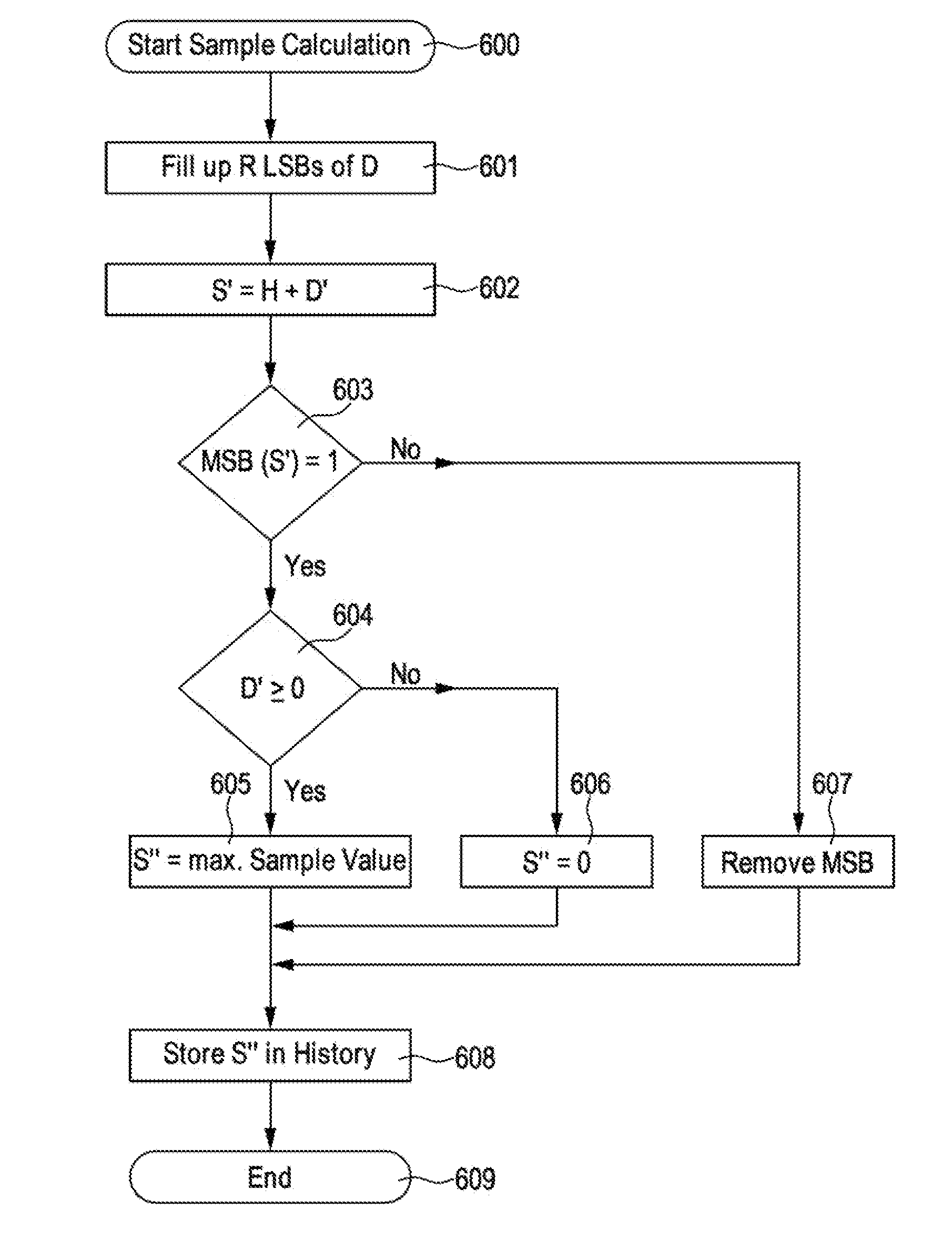
[0080]FIG. 1 shows a basic compression algorithm. The compression starts this step 100. In step 101 data is input from the data source like a CT scanner. Preferably a block of N input samples, wherein N is an integer number, is input and further processed together. In the following step 102, an appropriate mod for predicting the data is selected. The selection may be based on history like previously input data, preferably data which has been stored in history memory in step 111. With the selected model in step 103 the differences between the received data of input step 101 and the model D=S−H are calculated. If a required compression cannot be reached by the algorithm, an optional reduction of differences is performed in step 104. This step, calculating the reduced differences DR from the differences, D, may be called a difference reducer. By using these reduced differences, decompressed values are calculated in steps 108-110. First in step 108 reconstructed differences D′ are calcu...


PUM


Abstract

A compressor and decompressor for CT scanner data first performs a lossless compression of individual CT sample value. After this compression, the compression ratio CR is calculated. This is compared to a target compression ratio. If the target compression ratio is larger or equal than the achieved compression ratio, and additional lossy compression is performed by reducing the number of bits of the lossless compressed values. Immediately after such a lossy compression a lossy decompression is performed within the compressor and the decompressed values stored as history for the compressor keeping the compressor and decompressor in sync. This allows for a better quality of decompressed data while achieving a higher compression ratio.

Description

PRIORITY CLAIM[0001]This application claims priority from European Patent Application No. EP 12167757.9 filed on May 11, 2012, which is herein incorporated by reference in its entirety.BACKGROUND OF THE INVENTION[0002]1. Field of the Invention[0003]The present invention relates generally to the art of medical diagnostic imaging and baggage imaging and in particular to a method and apparatus for a computer tomography wherein the measurement data are compressed and possibly decompressed en route to the computer that reconstructs images of the scanned object.[0004]2. Description of Relevant Art[0005]In Computed Tomography (CT), raw data is acquired during a scan of an object irradiated by X-rays from an X-ray source from different directions (projections). The X-rays attenuated by the object are incident on a number of sensors (channels) that are arranged in multiple rows of a radiation detector. The number of rows is typically referred to as the number of slices.[0006]The X-ray source...

Claims


Application Information

Patent Timeline
Patent Type & Authority Patents(United States)
IPC IPC(8): G06K9/36H04N19/124H04N19/46H04N19/172H04N19/194H04N19/152
CPCH04N19/194H04N19/124H04N19/152H04N19/172H04N19/46
Inventor KAEMPFER, GIDEON
Owner XRING TECH