
Communication method, base station, communication system, and mobile terminal

a communication system and mobile terminal technology, applied in the direction of electrical equipment, broadcast service distribution, connection management, etc., can solve the problems of system load, control signal amount and frequency, etc., and achieve the effect of reducing system throughput, reducing useless allocation of resources, and reducing the amount of resources

Inactive Publication Date: 2015-10-13
MITSUBISHI ELECTRIC CORP
View PDF28 Cites 1 Cited by
  • Summary
  • Abstract
  • Description
  • Claims
  • Application Information

AI Technical Summary

Benefits of technology

The present invention provides a data communication method and a communication system that can efficiently allocate radio resources to mobile terminals and reduce the allocation of unnecessary resources. The method includes a base station that performs a persistent scheduling process and transmits a scheduling result to a mobile terminal in a predetermined notification cycle. The mobile terminal transmits a scheduling request signal to the base station and receives the allocated radio resources. The base station notifies the mobile terminal of the available radio resources for both talk-spurt (when the base station transmits voice information as voice packet data) and silent-period (when the base station transmits background noise data as voice packet data). The mobile terminal uses the allocated radio resources for the talk-spurt period and receives the voice packet data. The communication system includes a mobile terminal that transmits a scheduling request signal and performs continuous reception to reduce time delays.

Problems solved by technology

A challenge is therefore to change the allocation of radio resources and the MCS according to the data rate and the quality of data which vary at an arbitrary timing in order to make effective use of the radio resources and maintain the communication path quality, and to also reduce useless resource allocation which is caused in that case, reduce the amount and frequency of control signals which are generated in the course of communications, and reduce the system load.
Another challenge is to provide a radio resource allocation method which makes it easy to stabilize the communication quality in order to reduce the occurrence of control signals in the course of communications.
A further challenge is to reduce the delay which is caused by an overhead or a receiving error of a control signal transmitted between the base station and the mobile terminal, thereby reducing the delay to a minimum so that the data can be reproduced in real time.

Method used


Image

  • Communication method, base station, communication system, and mobile terminal
  • Communication method, base station, communication system, and mobile terminal
  • Communication method, base station, communication system, and mobile terminal

Examples


embodiment 1

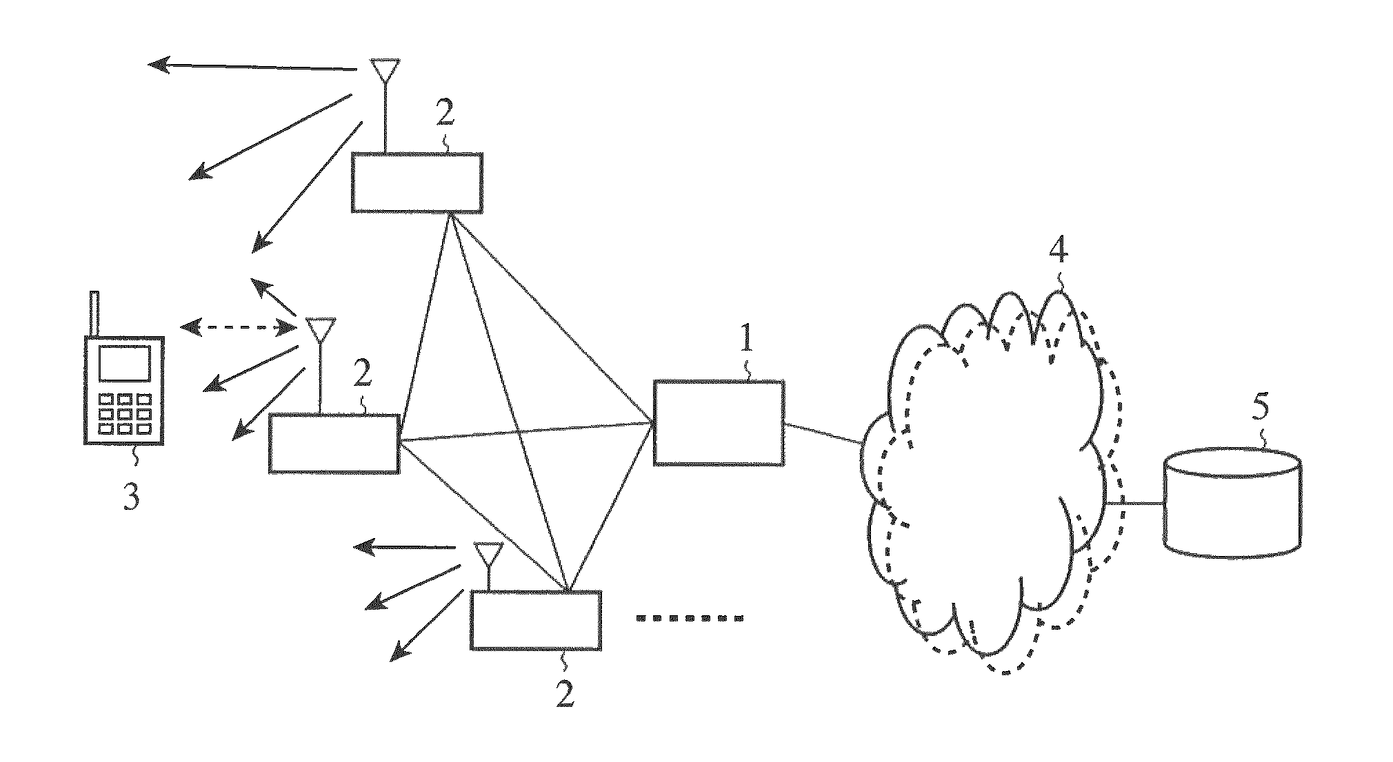
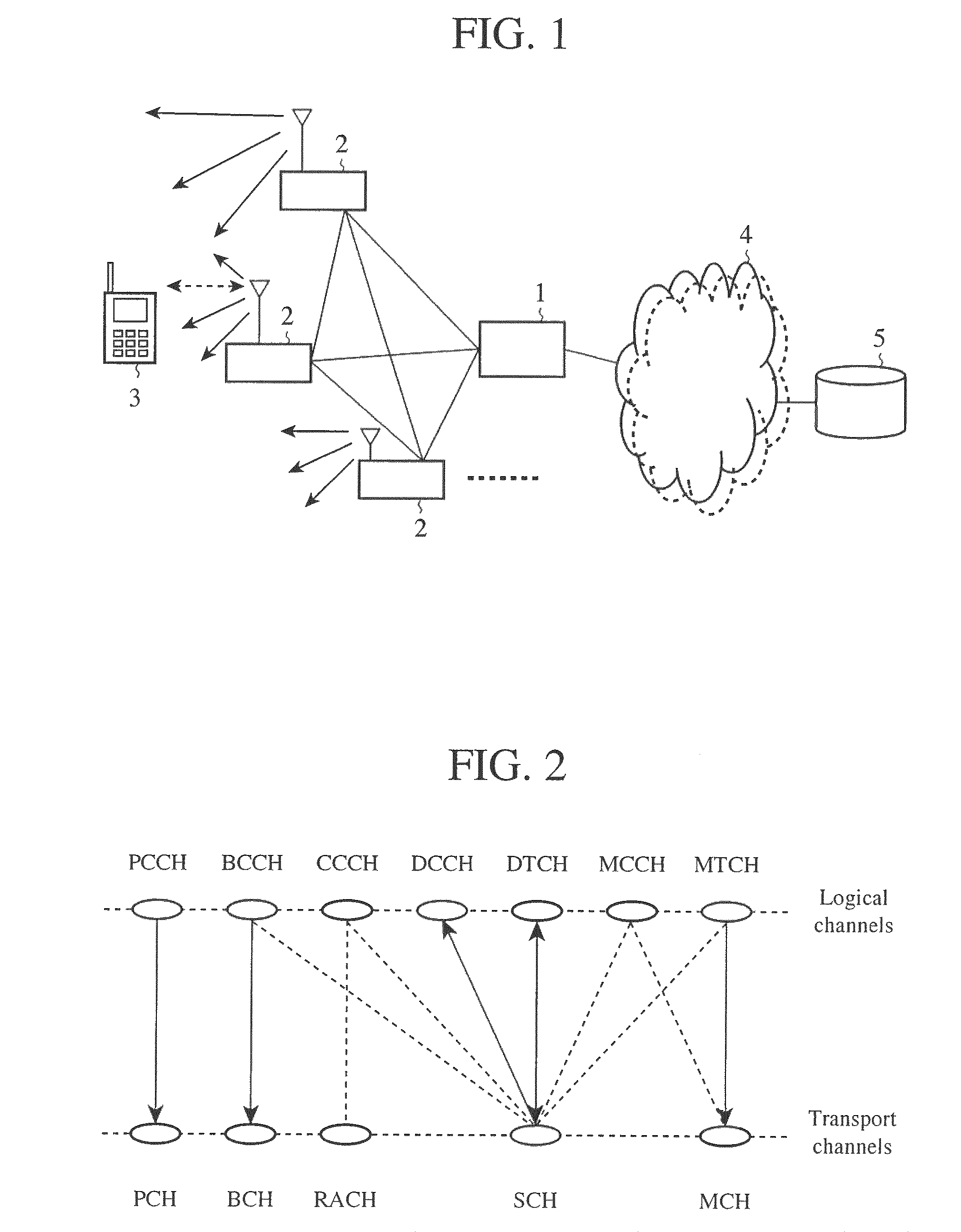
[0048]FIG. 1 is an explanatory drawing showing the structure of a mobile communication system which complies with LTE. In FIG. 1, an aGW 1 performs transmission and reception of control data and user data with a plurality of base stations (eNB) 2, and a base station 2 transmits and receives data to and from a plurality of mobile terminals (UE) 3. Between a base station 2 and a mobile terminal 3, broadcast information, information used for processing a call, individual control data, individual user data, control data for E-MBMS, user data, and so on are transmitted. It has also been studied that base stations 2 communicate with each other. A base station 2 has uplink and downlink schedulers. These schedulers of a base station 2 enable transmission and reception of data between the base station 2 and each mobile terminal 3, and carry out scheduling for improvements in the throughput of each mobile terminal 3 and that of the whole mobile communication system.

[0049]A E-MBMS provides a b...

embodiment 2

[0068]In above-mentioned Embodiment 1, the method of disposing a channel exclusive for silent period for transmission of silent data, and allocating the data to be transmitted during a silent state to the channel exclusive for silent period is disclosed. In contrast, in this Embodiment 2, a method of allocating data to be transmitted during a silent state to a part of resources on a frequency axis which was allocated during a talk spurt without disposing any channel exclusive for silent period will be disclosed.

[0069]FIG. 10 is an explanatory drawing showing resource allocation for a downlink. The method of allocating a part of resources on the frequency axis, which was allocated during a talk spurt, during a silent state for a downlink is shown in FIG. 10. Each open box with a black frame shows a resource block (RB) which is allocated in dynamic scheduling, and each diagonally shaded box shows a resource to which a VoIP service of a certain mobile terminal (for example, the UE-A or...

embodiment 3

[0076]In the nonpatent reference 5, the use of frequency hopping in uplink (UL, Uplink) data transmission for which persistent scheduling is carried out is studied. However, nothing about a concrete hopping method of implementing frequency hopping is disclosed in the nonpatent reference 5. Therefore, nothing about a method of controlling frequency hopping is disclosed in the nonpatent reference 5. In this Embodiment 3, a concrete hopping method of implementing frequency hopping will be explained. In order to use frequency hopping in transmission of uplink data for which persistent scheduling is performed, it is preferable that a mobile terminal (UE) and a base station (eNB, eNodeB) share control of the frequency hopping. In this case, a further advantage can be provided. Unless the mobile terminal and the base station share control of the frequency hopping, the base station has to allocate uplink radio resources to the mobile terminal every time when frequency hopping is carried out...


PUM


Abstract

In accordance with the present invention, in a case of using persistent scheduling, when detecting a transition from a talk state to a silent state, resources to be allocated during a silent state are allocated to a channel exclusive for silent period, and the resources which have been allocated to a mobile terminal during the talk spurt are released. Therefore, the useless allocation of resources can be reduced, and the throughput of the system can be improved.

Description

FIELD OF THE INVENTION[0001]The present invention relates to a communication system which is called “long term evolution” (“Long Term Evolution” LTE), a base station and a mobile terminal which construct this communication system, a method of controlling communications between the base station and the mobile terminal at the time of communications, and a communication method of communicating a control signal.BACKGROUND OF THE INVENTION[0002]Commercial services which employ a W-CDMA (Wideband Code Division Multiple Access) method which is included in communication methods called a third generation were started in Japan since 2001. Furthermore, a service with HSDPA (High Speed Down Link Packet Access) which implements a further improvement in the speed of data transmission using downlinks (a dedicated data channel and a dedicated control channel) by adding a channel for packet transmission (HS-DSCH: High Speed-Downlink Shared Channel) to the downlinks has been started. Currently, anHSU...

Claims


Application Information

Patent Timeline
Patent Type & Authority Patents(United States)
IPC IPC(8): H04W4/10H04W76/00H04W72/00H04W88/02H04W76/04H04W72/12H04W72/04H04W4/06
CPCH04W4/10H04W76/005H04W72/005H04W88/02H04W72/12H04W76/04H04W76/048H04W72/04H04W72/1263H04W76/28H04W76/45H04W88/08H04W72/30H04W76/20H04W4/06
Inventor TADA, KEIKOMOCHIZUKI, MITSURUMAEDA, MIHOIWANE, YASUSHI
Owner MITSUBISHI ELECTRIC CORP
Learn More