Hybrid power supply architecture for supplying mechanical power to a rotor and managed from the on-board network of a rotorcraft

a technology of mechanical power and rotorcraft, which is applied in the field of rotary wing aircraft equipment, can solve the problems of not being able to design an architecture for delivering mechanical power to the rotor of the rotor, and the detriment of simplifying, so as to avoid excessive loading of the rotorcraft and be simple in structur

Active Publication Date: 2015-10-20
EUROCOPTER
View PDF23 Cites 26 Cited by
  • Summary
  • Abstract
  • Description
  • Claims
  • Application Information

AI Technical Summary

Benefits of technology

[0041]The present invention also more particularly seeks to provide such an architecture that is simple in structure and that avoids excessively loading the rotorcraft, enabling the architecture to be installed without major structural modification on any type of rotorcraft.

Problems solved by technology

A problem raised lies in reconciling delivering top-up mechanical energy from a reversible electric machine in order to drive the rotor, with safe working of the on-board network faced with the electricity needs of the rotorcraft.
The availability of this quantity of electrical energy must not be obtained to the detriment of attempts at simplifying the hybrid power plant architecture and must take account of the electrical energy needs of numerous pieces of equipment and accessories that might be fitted to the rotorcraft.
Consequently, it appears not to be easy to design an architecture for delivering mechanical power to a rotorcraft rotor from hybrid energy sources while complying with all of the above-mentioned constraints.

Method used


Image

  • Hybrid power supply architecture for supplying mechanical power to a rotor and managed from the on-board network of a rotorcraft
  • Hybrid power supply architecture for supplying mechanical power to a rotor and managed from the on-board network of a rotorcraft
  • Hybrid power supply architecture for supplying mechanical power to a rotor and managed from the on-board network of a rotorcraft

Examples


Embodiment Construction

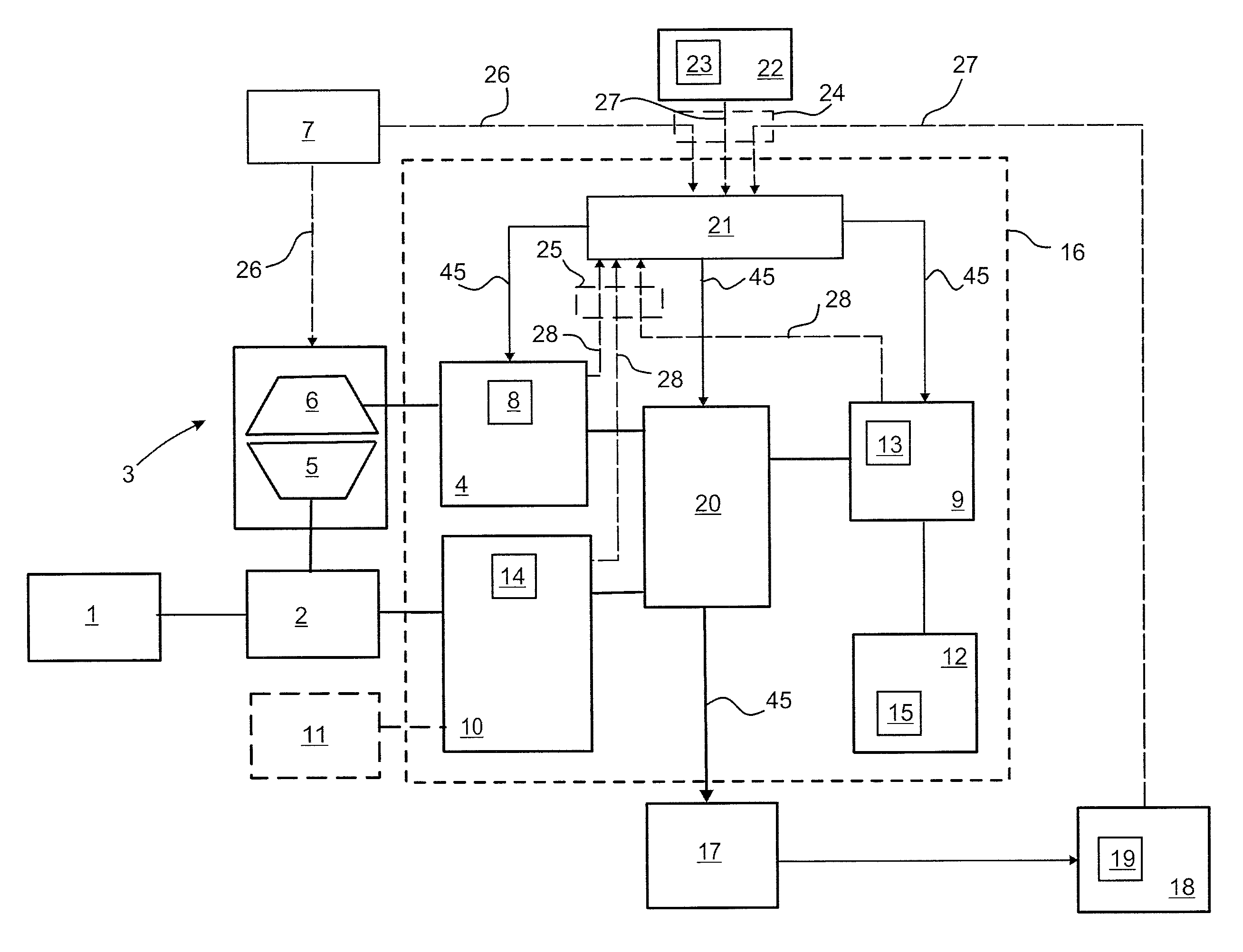
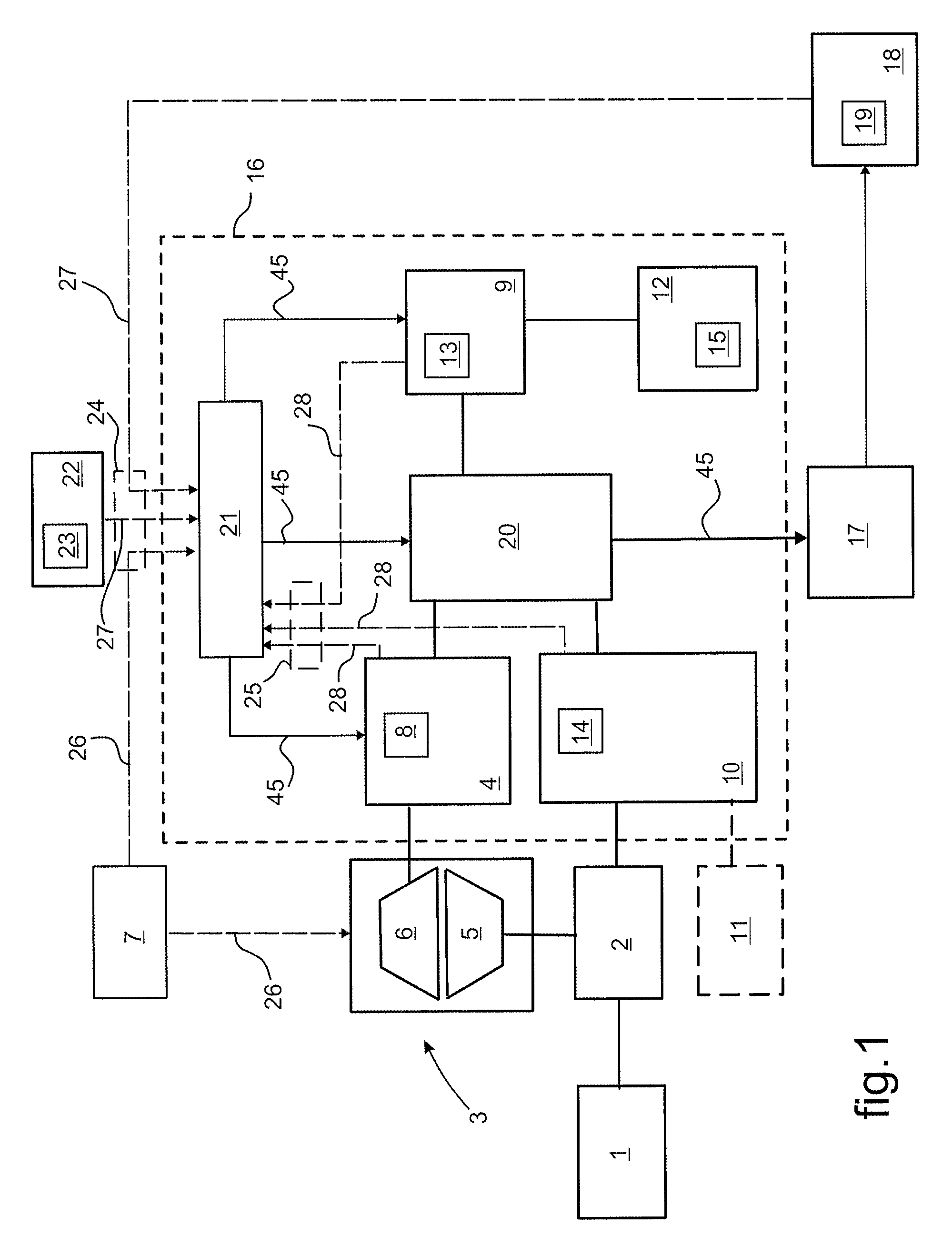
[0071]In FIG. 1, a rotorcraft rotor 1 is driven in rotation from a main gearbox (MGB) 2 that is itself driven by two mechanical drive sources 3 and 4. A first drive source is constituted by a combustion engine 3, and more particularly by a turboshaft engine including a gas generator 6 for driving a free turbine 5 in rotation, which free turbine is mechanically engaged with the MGB 2. The second drive source is constituted by a reversible electrical machine 4 engaged with the engine 3, and more particularly with its gas generator 6. The engine 3 and the reversible electric machine 4 are fitted with respective means 7 and 8 for regulating their operating mode.

[0072]A store of electrical energy 9 is potentially supplied with electrical energy by the reversible electric machine 4 and by an electricity generator 10 that is driven from the MGB 2, or from any other mechanical power source 11 of the rotorcraft. The electrical energy store 9 is also potentially supplied with energy from an i...


PUM


Abstract

An architecture for a hybrid power plant for driving a rotorcraft rotor (1). The rotorcraft is fitted with an electrical energy distribution network (17) for distributing electrical energy from a management network (20) that is interposed between the distribution network (17) and electrical energy sources (4, 9, 10). A management computer (21) takes account of information about the working of a combustion engine (3) for driving the rotor (1), about the working of the electrical energy sources (4, 9, 10) fitted to the rotorcraft and including an energy store (9), a reversible electric machine (4), and an electricity generator (10) engaged with the combustion engine, and about the electrical energy needs of the electricity distribution network (17). Electrical energy is distributed selectively by the management computer (21) via the management circuit (20) and to the distribution circuit (17) depending on priorities of maintaining safe flight of the rotorcraft and providing drive assistance to the engine (3) as produced by the reversible electric machine (4).

Description

CROSS REFERENCE TO RELATED APPLICATIONS[0001]This application claims priority to French patent application No. FR 12 01974 filed on Jul. 12, 2012, the disclosure of which is incorporated in its entirety by reference herein.BACKGROUND OF THE INVENTION[0002](1) Field of the Invention[0003]The present invention relates to the field of equipment for rotary wing aircraft, in particular for helicopters, and it relates to feeding energy to members that are fitted to the rotorcraft. Said members are more particularly power members such as at least one power plant for driving a rotor in rotation, and accessories and / or pieces of equipment that are useful for the working of the rotorcraft.[0004]The present invention relates more specifically to architectures for supplying a rotor fitted to a helicopter or an analogous rotary wing aircraft with mechanical power derived from hybrid energy sources, and for managing this power supply by means of an on-board electrical network of the rotorcraft.[0...

Claims


Application Information

Patent Timeline
Patent Type & Authority Patents(United States)
IPC IPC(8): B64D41/00B64C27/12B64D27/24B64D31/14B64D27/02
CPCB64D31/14B64C27/12B64D27/24B64D2027/026B64D2221/00Y02T50/64Y02T50/60
Inventor ROGGEMANS, EMMANUELLELOGEAIS, JEAN-FRANCOIS
Owner EUROCOPTER
Why Eureka
Try Eureka