Sensor clip assembly for an optical monitoring system

a technology of optical monitoring and sensor clip, applied in the field of optical monitoring systems, can solve the problems of more complex fittings such as spline fittings, and achieve the effects of avoiding cable noise, facilitating integration into other electronic components, and introducing additional noise to the signal

Active Publication Date: 2015-11-03
FRESENIUS MEDICAL CARE HLDG INC
View PDF121 Cites 6 Cited by
  • Summary
  • Abstract
  • Description
  • Claims
  • Application Information

AI Technical Summary

Benefits of technology

[0018]As mentioned, a primary advantage of the invention is that the technology for optically monitoring the patient's hematocrit or oxygen saturation level can now be easily integrated into other electronic or medical equipment without requiring custom designed circuit boards to be integrated into the respective host devices. Implementing the data acquisition process and the mathematical conversion of the detected signals into serial (e.g. USB) data signals on circuit boards located on the sensor clip assembly provides several additional advantages, as well. First, it is advantageous to collect and convert the extremely small current (μA) signals from the silicon detector diode(s) and the indium gallium arsenide diode(s) without allowing the signals to be transmitted over a relatively long distance through wires, which introduce additional noise to the signal. Rather, the small signals are processed at the receiving point and the resulting measurements are quantified by a microprocessor and then transmitted by high level digital signaling to the host which is highly immune to cable noise. Further, a balanced data signal (e.g. USB) maintains the integrity of the transmitted data even better. Another advantage of the invention is that processing current signals (μA) from the detector diode(s) at the receiving point enables the system to drive the LED emitters with lower electrical currents. The use of lower LED drive currents not only reduces heat generation but also tends to extend the useful calibrated life of the LEDs.
[0019]Another advantage is that a sensor clip assembly made in accordance with the invention can be constructed to be a semi-durable device. Once the sensor clip falls out of calibration and can no longer be field calibrated, it will often be practical to simply replace the sensor clip assembly rather than return the sensor clip to the manufacturer for recalibration. The clinic can therefore continue operations without having to return systems or custom circuit boards to the manufacture for calibration.

Problems solved by technology

However, under some conditions, more complex fits such as a spline fit must be used.

Method used


Image

  • Sensor clip assembly for an optical monitoring system
  • Sensor clip assembly for an optical monitoring system
  • Sensor clip assembly for an optical monitoring system

Examples


Embodiment Construction

[0026]FIG. 6 is a perspective view showing a sensor clip assembly for an optical blood monitor constructed in accordance with the preferred embodiment of the invention.

[0027]FIG. 7 is a view similar to FIG. 6 with the housings for the sensor clip assembly drawn in phantom in order to show internal components of the sensor clip assembly.

[0028]FIG. 8 is a cross-sectional view taken along line 8-8 in FIG. 6.

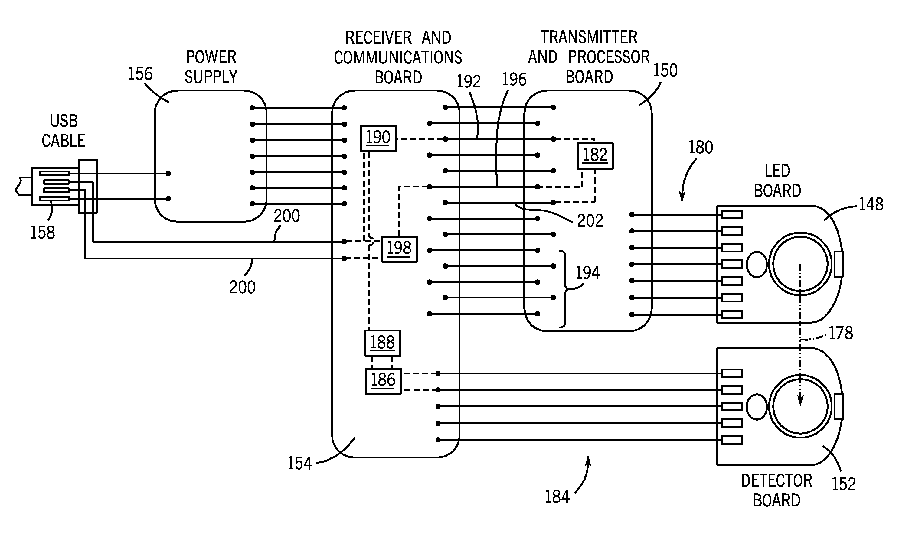
[0029]FIG. 9 is a schematic view illustrating the transmission and processing of data on the components in the sensor clip assembly illustrated in FIGS. 6 through 8.

DETAILED DESCRIPTION

Prior Art

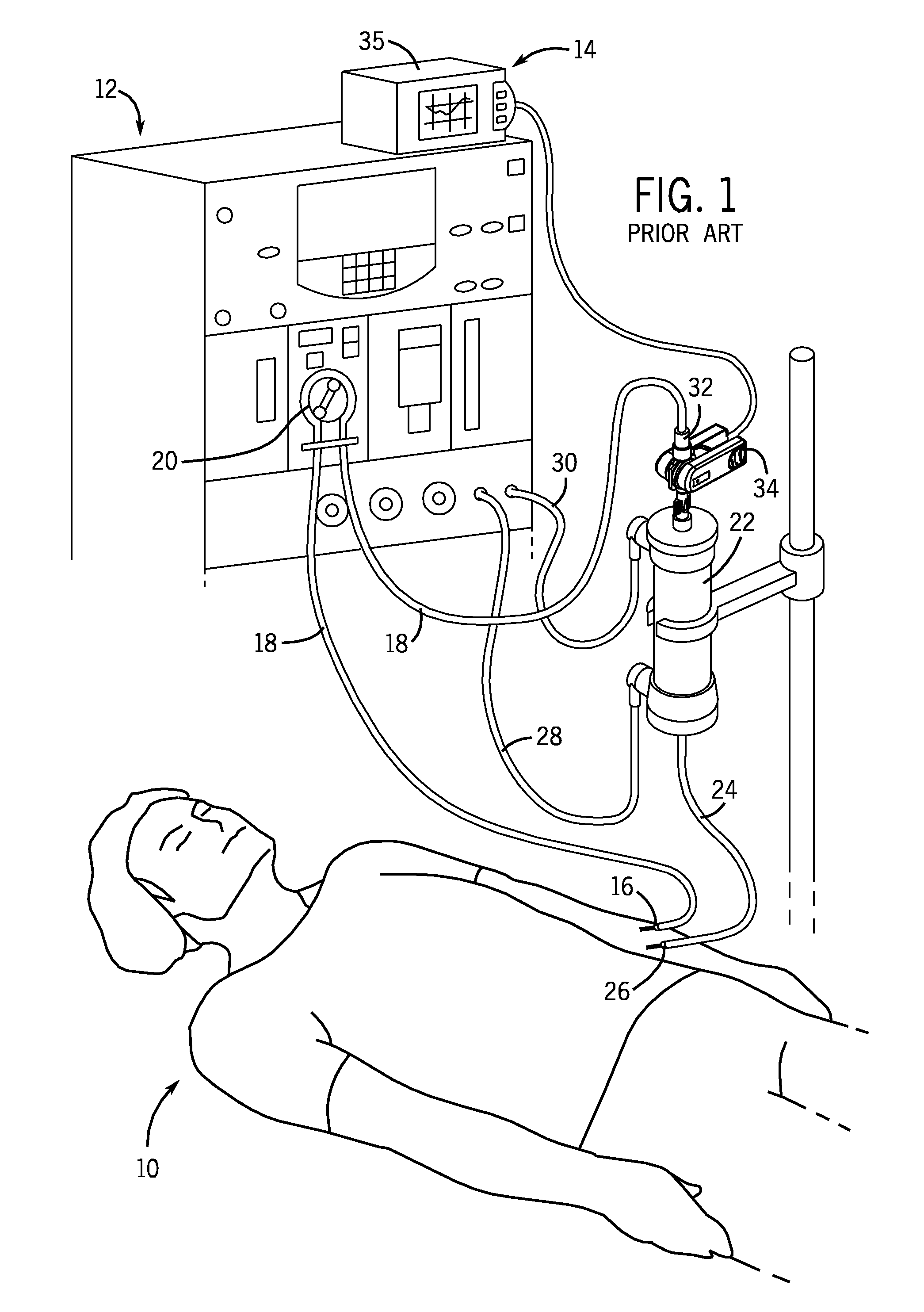
[0030]FIG. 1 illustrates a patient 10 undergoing hemodialysis treatment with a conventional hemodialysis system 12, and also illustrates a non-invasive, optical blood monitor 14 (i.e., a CRIT-LINE® optical blood monitoring system sold by the assignee). A typical hemodialysis clinic will have several hemodialysis systems 12 for treating patients.

[0031]An input needle or catheter 16 is inserted...


PUM


Abstract

A sensor clip assembly for an optical blood monitoring system includes a circuit board with a microprocessor that is programmed with a ratiometric model to calculate hematocrit and / or oxygen saturation levels of a patient.

Description

CROSS REFERENCE TO RELATED APPLICATION[0001]This application claims priority from Provisional U.S. Patent Application No. 61 / 414,654, filed Nov. 17, 2010.FIELD OF THE INVENTION[0002]The invention relates to optical monitoring systems, and more specifically systems for monitoring the presence or concentration of constituents in blood. The invention is particularly useful for the real-time measurement of hematocrit and / or oxygen saturation levels when monitoring a patient during hemodialysis or other procedure involving extracorporeal blood flow.BACKGROUND[0003]Patients with kidney failure or partial kidney failure typically undergo hemodialysis treatment in order to remove toxins and excess fluids from their blood. To do this, blood is taken from a patient through an intake needle or catheter that draws blood from a blood vessel located in a specifically accepted access location (for example, a shunt surgically placed in an arm, thigh, subclavian, etc.). The needle or catheter is con...

Claims


Application Information

Patent Timeline
Patent Type & Authority Patents(United States)
IPC IPC(8): A61B5/1455A61B5/145A61M1/36A61B5/00
CPCA61M1/367A61B5/1455A61B5/14535A61B5/6866A61M1/36A61M1/3609A61M2205/3306A61M2205/3313A61M2230/207
Inventor BARRETT, LOUIS L.PETERSON, DAVID W.HUDKINS, N. DIANESTOWELL, MATTHEW A.SAMMANN, KRISTIAN A.JENSEN, BEMJAMIN D.COX, DOUGLAS L.LAW, PERRY N.GLAITTLI, RONALD S.
Owner FRESENIUS MEDICAL CARE HLDG INC
Why Eureka
Try Eureka