Downhole telemetry signalling apparatus

a telemetry and signalling technology, applied in the field of downhole telemetry apparatus, can solve the problems of difficult to know with reasonable accuracy where the drill bit is located, the target location uncertainty of about 3.0 meters, and the intrinsic limit of the mud pulse system to a few bits per second

Active Publication Date: 2015-11-10
ZIENTARSKI MARIUSZ THOMAS
View PDF10 Cites 15 Cited by
  • Summary
  • Abstract
  • Description
  • Claims
  • Application Information

AI Technical Summary

Problems solved by technology

Given the non-homogeneity of the underlying geological structure, and the tendency for drill bits to wander, it may be difficult to know with reasonable accuracy where the drill bit may be.
Such an error translates into a target location uncertainty of about 3.0 meters per 1000 meters along the borehole.
It is well known that mud pulse systems are intrinsically limited to a few bits per second due to attenuation and spreading of pulses.”
It has been found, however, that this type of system requires a special drill pipe and special tool joint connectors which substantially increase the cost of a drilling operation.
Also, these systems are prone to failure as a result of the abrasive conditions of the mud system and the wear caused by the rotation of the drill string.”
It has been found, however, that the very low intensity of the signal which can be generated downhole, along with the acoustic noise generated by the drilling system, makes signal detection difficult.
Reflective and refractive interference resulting from changing diameters and thread makeup at the tool joints compounds the signal attenuation problem for drill pipe transmission.”
It has been found, however, that in deep or noisy well applications, conventional electromagnetic systems are unable to generate a signal with sufficient intensity to be recovered at the surface.”
As the ratio drops, it becomes more difficult to recover or reconstruct the signal.
While increasing the power of the transmitted signal is an obvious way of increasing the signal to noise ratio, this approach is limited by batteries suitable for the purpose and the desire to extend the time between battery replacements.

Method used


Image

  • Downhole telemetry signalling apparatus
  • Downhole telemetry signalling apparatus
  • Downhole telemetry signalling apparatus

Examples


Embodiment Construction

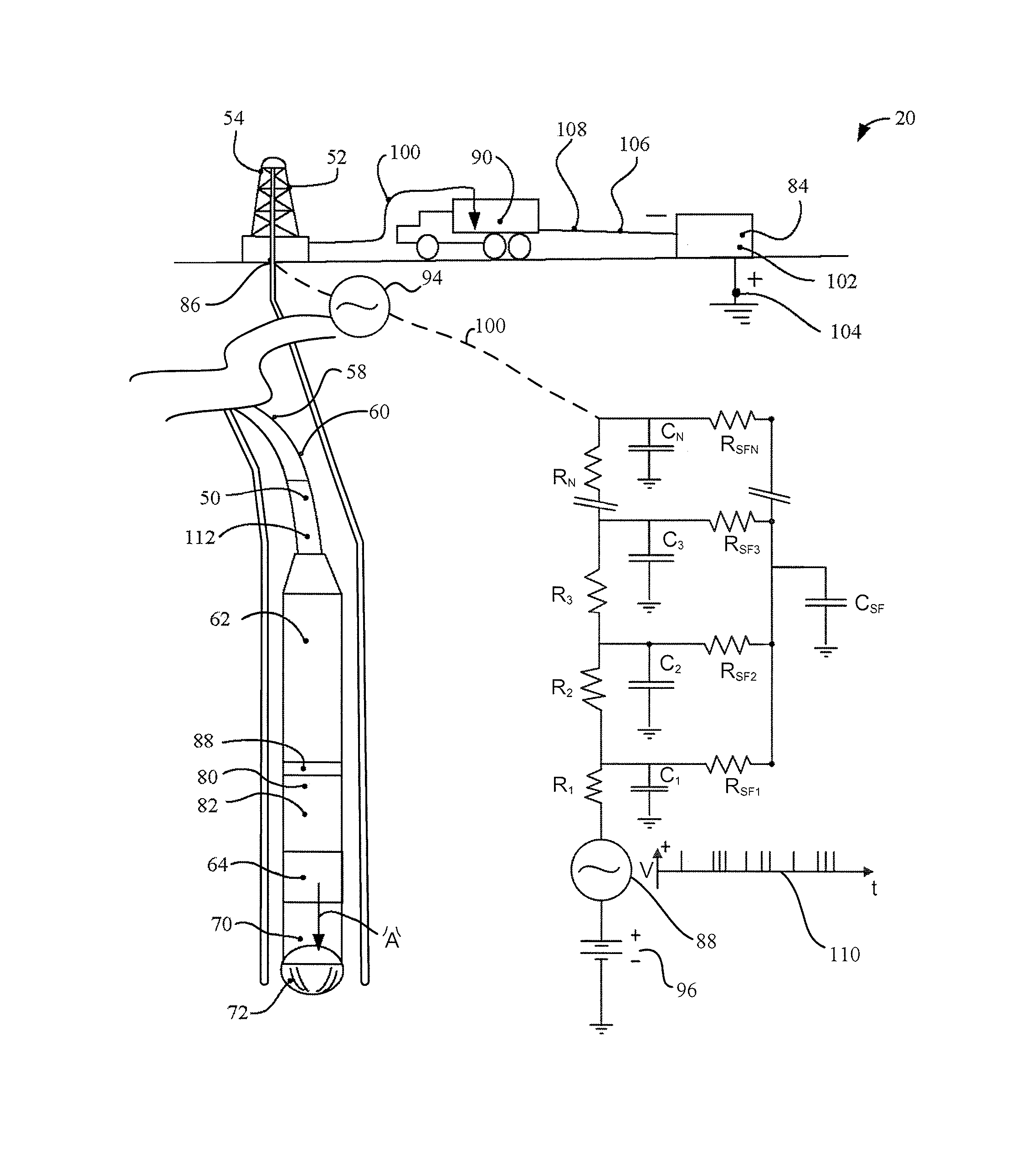
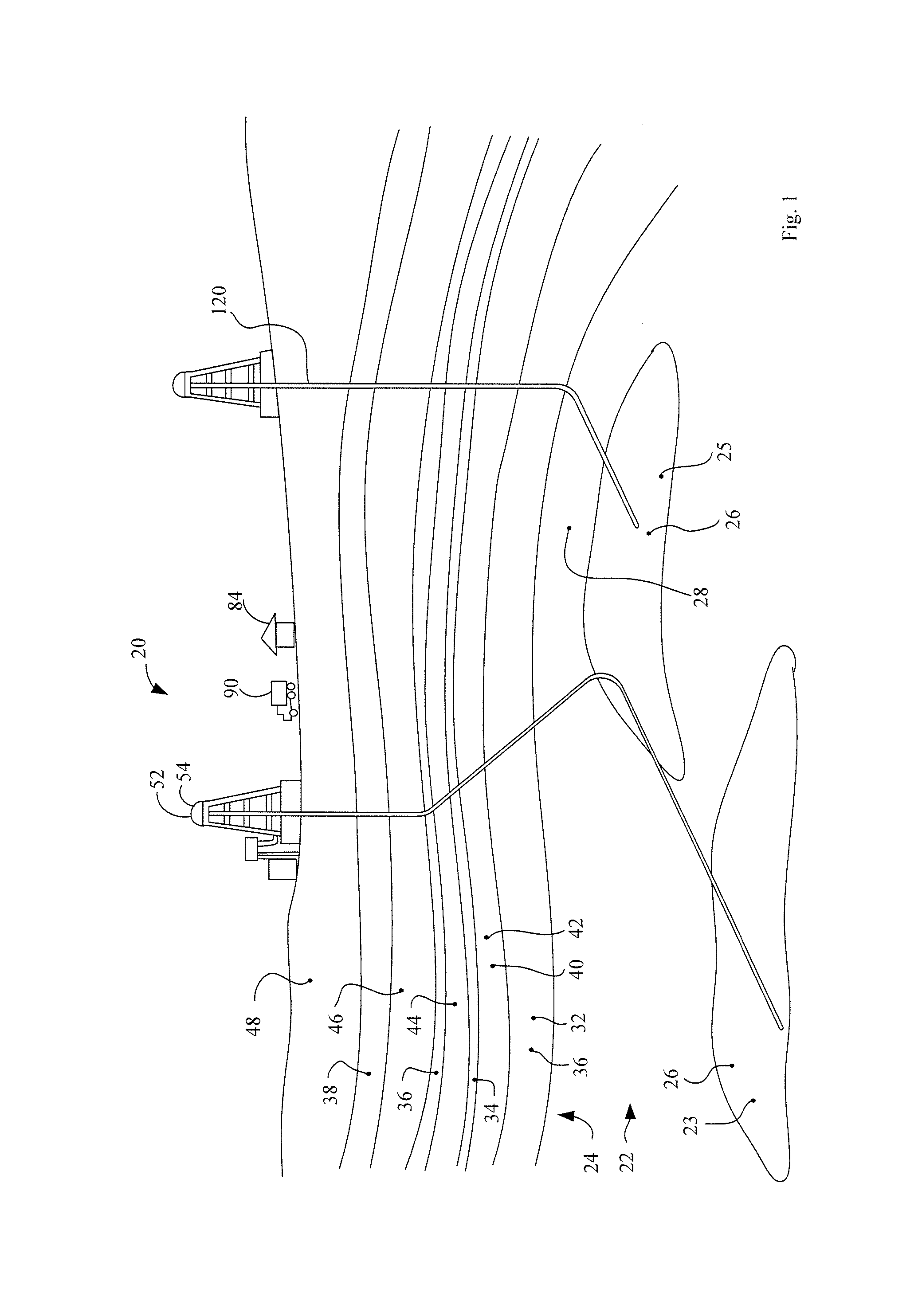
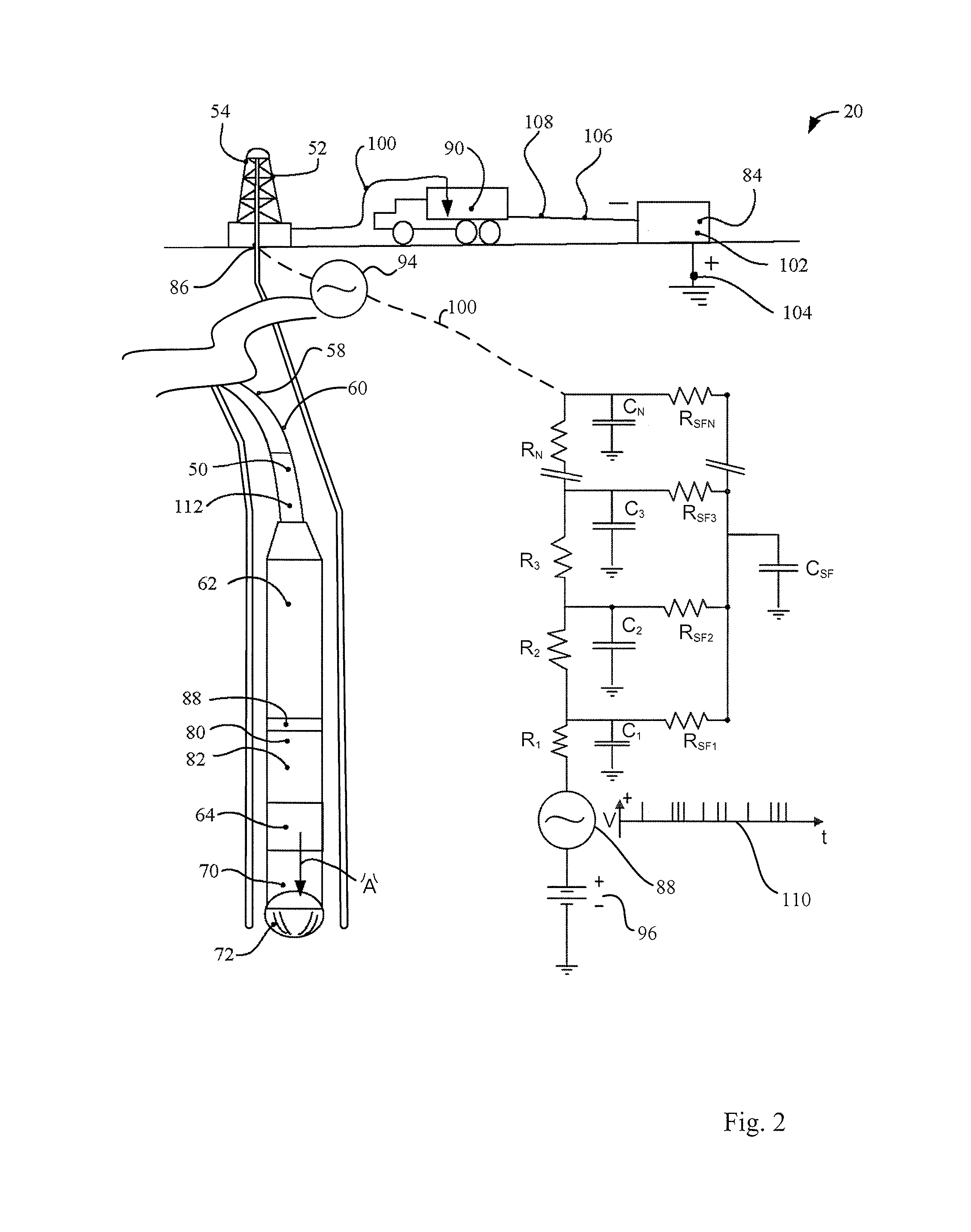
[0033]The description that follows, and the embodiments described therein, are provided by way of illustration of an example, or examples, of particular embodiments of the principles of the present invention. These examples are provided for the purposes of explanation, and not of limitation, of those principles and of the invention. In the description, like parts are marked throughout the specification and the drawings with the same respective reference numerals. The drawings are not necessarily to scale.

[0034]The terminology used in this specification is thought to be consistent with the customary and ordinary meanings of those terms as they would be understood by a person of ordinary skill in the art in North America. While not excluding interpretations based on other sources that are generally consistent with the customary and ordinary meanings of terms or with this specification, or both, the Applicant expressly excludes all interpretations that are inconsistent with this specif...


PUM


Abstract

A well-bore downhole data logging signal transmission apparatus having: a signal transmitter at a drill bit on a drill string; a receiver at a drill bore head, a generator places a carrier current on the drill string with the drill bit; the transmitter places signal pulses; the receiver senses the pulses; the pulses have a duration less than 10 ms.

Description

[0001]This application claims the benefit under 35 USC 120 of U.S. Provisional patent application Ser. No. 61 / 559,402 filed Nov. 14, 2011, and claims also claims the benefit under 35 USC 119 of Canadian Patent Application 2,746,875 filed Jul. 19, 2011, the specifications and drawings of those applications being incorporated herein by reference.FIELD OF THE INVENTION[0002]This invention relates to the field of downhole telemetry apparatus, and methods of use of such apparatus.BACKGROUND[0003]The determination of the location of a distant subterranean object may be of considerable commercial importance in the fields of well drilling, tunnel boring, pipeline laying under rivers or other surface obstructions, hard rock mining, and so on. In hydrocarbon extraction, a drill string may be 3 to 6 inches in diameter, and yet may extend many thousands of feet into the ground. Given the non-homogeneity of the underlying geological structure, and the tendency for drill bits to wander, it may be...

Claims


Application Information

Patent Timeline
Patent Type & Authority Patents(United States)
IPC IPC(8): E21B47/12H04B13/02
CPCE21B47/12E21B47/122H04B13/02E21B47/13
Inventor ZIENTARSKI, MARIUSZ THOMAS
Owner ZIENTARSKI MARIUSZ THOMAS
Why Eureka
Try Eureka