
Cartridge with rapidly increasing sequential ignitions for guns and ordnances

a technology of sequential ignition and cartridge, which is applied in the direction of cartridge ammunition, explosives, weapons, etc., can solve the problems of reducing adding unnecessary cost and complexity to manufacturing the desired cartridge-based solution, and reducing the efficiency of the full length of the desired barrel for acceleration, etc., to achieve efficient increase the sequential detonation, facilitate the expulsion of hyper-velocity projectiles, and increase the effect of velocity and pressure curv

Active Publication Date: 2015-11-10
COFFMAN II CHARLES W
View PDF11 Cites 4 Cited by
  • Summary
  • Abstract
  • Description
  • Claims
  • Application Information

AI Technical Summary

Benefits of technology

This patent is about a new method of using propellant in cartridges to increase the velocity and pressure curve of projectiles. The method involves compressing and stacking layers of powder to control the burn rate and increase the energy density. The layers are compressed to a specified degree and the burn rate of each layer is controlled by the compression. This allows for more efficient use of the energy and reduces the pressure on the chamber and barrel. The method also involves igniting the powder layers in stages to create a more uniform linear acceleration of the projectile. The result is higher velocities and more compact cartridges.

Problems solved by technology

Following that pressure spike, the ability to accelerate a projectile using the full length of a desired barrel is greatly diminished, resulting in an untapped potential of the barrel length for optimized acceleration.
Both methods add unnecessary cost and complexity to manufacturing the desired cartridge-based solutions.
Most stratified propellant approaches utilize a lacquer or resin that must cure prior to loading the next layer of powder, which is undesirable during commercial manufacturing.
These methods can reduce the case volume and present mass production challenges in the insertion process.
Powders with retardants are less efficient, more costly, and are limited in their ability to provide ever-increasing pressure for the full length of a barrel.
This method, however, has been minimally effective, as a flashover of both powders can occur.
The second layer of powder can only burn slightly faster, or the flashover of the two powders can create dangerous pressures and lower velocities.
Igniting the propellant(s) creates a pressure spike, which eventually fades, thereby diminishing the ability to accelerate a projectile using the full length of a desired barrel.
This results in untapped potential of the barrel length for optimizing acceleration.
This creates high outward pressures and dangerous (“detonation”) issues when the primer flashes over high-energy low-volume powder charges, causing a rapid increase in pressure sufficient to blow up a firearm.
While significant advancements have been made in the design and manufacture of modern day propellants, the full potential of a given powder is still untapped due to a single source of detonation from the chamber.
However, most current methods lack the ability to increase the force applied to the projectile at its most critical stage of having obtained minimal velocity, beyond that provided by the initial pressure spike, or by the delay of the pressure level.
While in many cases such propellants are more desirable, they tend to burn less efficiently, resulting in a dirtier, less efficient burn.
They may also ignite in an inconsistent manner, which can result in a dangerous situation such as a bullet remaining lodged in the barrel.
The application of a highly compressed powder column reduces the burn rate, and may force one or more of the powder layers to ignite with the projectile down the barrel.

Method used


Image

  • Cartridge with rapidly increasing sequential ignitions for guns and ordnances
  • Cartridge with rapidly increasing sequential ignitions for guns and ordnances
  • Cartridge with rapidly increasing sequential ignitions for guns and ordnances

Examples


Embodiment Construction

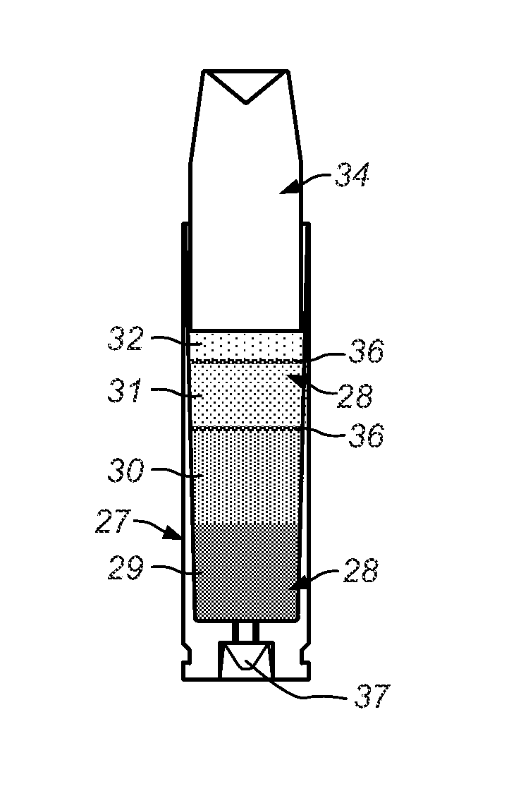
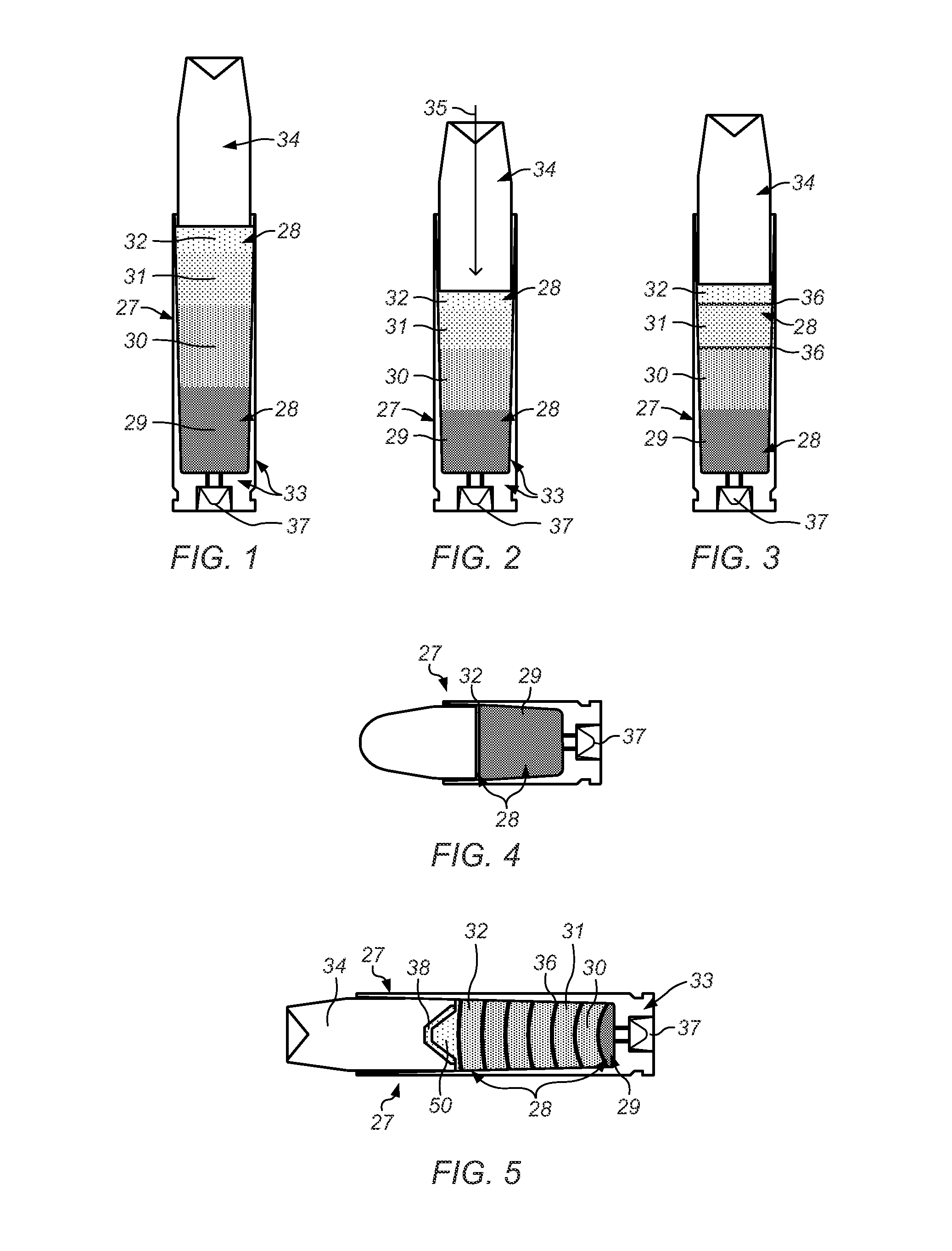
[0063]In one set of embodiments, a cartridge may be loaded with a powder column of stratified or stacked layers of propellant, whereby each powder layer in the powder column is over-compressed to a specified degree, and the burn rate or modifier between layers may be controlled by the specified degree of over-compression applied to each respective powder layer of the powder column. More broadly, rapidly increasing faster powders may be provided in sequence, and instead of using complex barrier methods, the rate of burn between layers may be controlled by the volume of the layer and the amount of compression introduced to the layer.

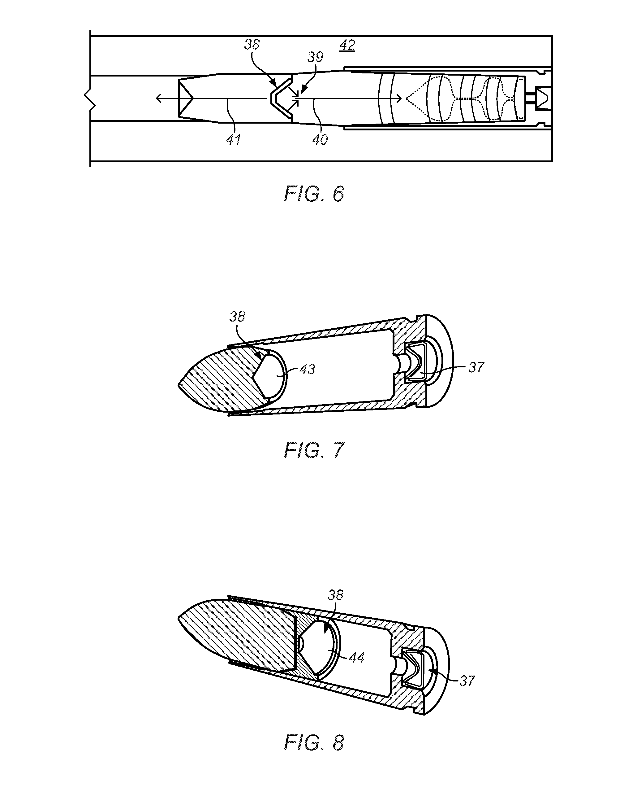
[0064]Rather than attempting to extend the force applied from the chamber down the full length of a barrel, the application of a highly compressed powder column reduces the burn rate, and in some cases forces one or more of the powder layers to launch with the projectile down the barrel. In doing so, the powder column is forced to burn similar to the manne...


PUM

PropertyMeasurementUnit
pressureaaaaaaaaaa
volumeaaaaaaaaaa
shapeaaaaaaaaaa

Abstract

A cartridge may be loaded with a powder column containing stratified, stacked layers of propellant, each powder layer over-compressed to a specified degree, with the burn rate controlled by the specified degree of over-compression applied to each respective powder layer. The application of a highly compressed powder column reduces the burn rate, and may force one or more of the powder layers to launch with the projectile down the barrel. Accordingly, the powder column is forced to burn in a manner similar to fuel burning in a solid fuel rocket engine. This greatly reduces the pressure(s) developed in the chamber, and permits the force of the burning powder to be efficiently focused on forward propulsion. The rapidly increasing set of sequential ignitions provides higher and higher energy densities with each subsequent ignition, and creates a more uniform linear acceleration of the projectile for the full length of the target barrel.

Description

PRIORITY CLAIM[0001]This application claims benefit of priority of U.S. provisional application Ser. No. 61 / 621,040 titled “Cartridge with Rapidly Increasing Sequential Ignitions for Guns and Ordnances”, filed Apr. 6, 2012, which is hereby incorporated by reference in its entirety as though fully and completely set forth herein.BACKGROUND OF THE INVENTION[0002]1. Field of the Invention[0003]This invention relates generally to cartridges for guns and ordnances, and more specifically to cartridges having rapidly increasing sequential ignitions.[0004]2. Description of the Related Art[0005]Most projectiles are conventionally accelerated using chamber-based systems, in which a pressure spike is created in a cartridge. Following that pressure spike, the ability to accelerate a projectile using the full length of a desired barrel is greatly diminished, resulting in an untapped potential of the barrel length for optimized acceleration. The most common approach to solving this problem has be...

Claims


Application Information

Patent Timeline
Patent Type & Authority Patents(United States)
IPC IPC(8): F42B5/26F42B5/16
CPCF42B5/26F42B5/16
Inventor COFFMAN, II, CHARLES W.
Owner COFFMAN II CHARLES W
Learn More