Device and method for 3D dose tracking in radiation therapy

a radiation therapy and 3d technology, applied in radiation therapy, radiation therapy, x-ray/gamma-ray/particle irradiation therapy, etc., can solve the problems of extending the treatment planning time required for each patient, difficult for operators to detect during the delivery possible deviations from the planned sequence of irradiation

Active Publication Date: 2015-12-01
ION BEAM APPL
View PDF24 Cites 18 Cited by
  • Summary
  • Abstract
  • Description
  • Claims
  • Application Information

AI Technical Summary

Benefits of technology

[0059]Accordingly, many advantages are reached by using the present invention. In fact the embodiments of the invention allow to:

Problems solved by technology

Treatment planning for IMRT is obviously more complex than for conventional radiation therapy, extending treatment planning time required for each patient.
Unlike the conventional delivery, the complexity of the IMRT treatments makes it difficult for the operators to detect during the delivery possible deviations from the planned sequence of irradiations.
The high dose gradients in IMRT fields make single point-dose measurements inadequate in verifying the significantly non uniform dose distributions.
Errors in the individual IMRT beam dose distributions calculated by treatment planning systems can occur because interleaf leakage of the multi-leaf collimator (MLC) is, for example, not accurately accounted for.
The potential for systematic errors in the transfer of MLC leaf sequence files from the treatment planning computer to the record and verify system, and in the mechanical accuracy of the MLC leaf movements during beam delivery further necessitates the use of accurate IMRT verification strategies.
However, no means are provided to take into account the changes in the patient's anatomy occurring inbetween fractions.
It is evident that such a method is time-consuming and not accurate.
Furthermore, this method never addresses to the verification of the radiation apparatus before the actual treatment of a patient.
Again, no means are provided to take into account changes in patient's anatomy occurring inbetween fractions.
The disadvantage of this technique is that because the detector is positioned behind the patient, the detector signals are a mixture of primary photons and scattered photons (see caption to FIG. 2).
This is a very time consuming procedure.
Accordingly, no practical solution is proposed to provide an accurate radiation apparatus and dose verification method as well as to perform an easy and fast dose computation that overcomes the drawbacks above mentioned.

Method used


Image

  • Device and method for 3D dose tracking in radiation therapy
  • Device and method for 3D dose tracking in radiation therapy
  • Device and method for 3D dose tracking in radiation therapy

Examples


Embodiment Construction

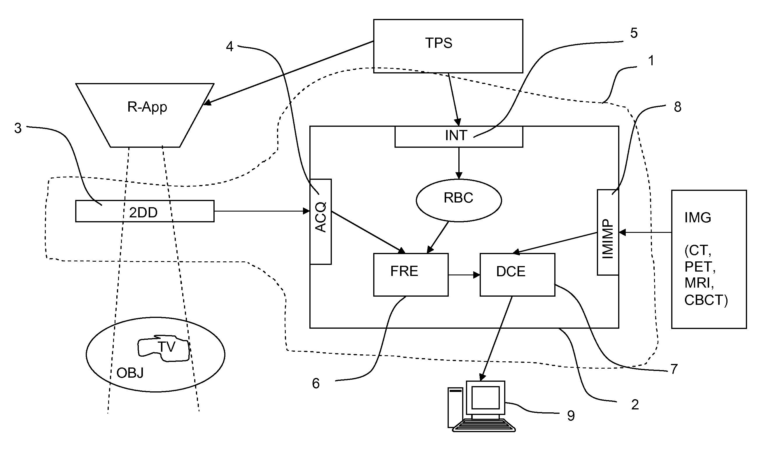
[0044]The present invention is intended to be used with a radiation therapy apparatus, which delivers high energy x-ray from an isocentric gantry linear accelerator, and especially with an IMRT apparatus wherein the beam modulation is accomplished by means of a multi leaf collimator (MLC) or by jaws.

[0045]A beam model is a mathematical description of a radiation therapy apparatus in general, which contains a number of parameters. These parameters take into account e.g. the characteristics of the accelerator (energy spectrum, lateral beam quality variations), the shapes and positions of the effective radiation sources, and the geometry and material of the beam shaping devices. A fluence computation algorithm is a set of mathematical rules which compute the fluence according to the beam model and a given parameter set. The representation of the computed fluence (units, coordinate systems) is such that it is compatible with additional computational procedures for computing deposited do...


PUM


Abstract

The present invention relates to a device and method for verification of the quality of a radiation beam in conformal radiation therapy, and in particular for IMRT (Intensity Modulated Radiation Therapy) applications. The actual 3D dose distribution in the patient is tracked during the course of the entire treatment by reconstructing the photon fluences from measured 2D detector responses during irradiation in conjunction with updated patient images.

Description

CROSS REFERENCE TO RELATED APPLICATIONS[0001]This application is a national phase application of International Application No. PCT / EP2009 / 055488, filed May 6, 2009, designating the United States and claiming priority to European Patent Application No. 08155748.0, filed May 6, 2008, both of which are incorporated by reference herein in their entirety.FIELD OF THE INVENTION[0002]The present invention relates generally to radiation therapy used to deliver radiation doses. More particularly, the present invention relates to a device and a method for 3D dose tracking during consecutive treatment fractions.STATE OF THE ART[0003]In the context of the present invention, radiation therapy means treatment by X-ray or electron beams. The present invention is of particular interest for Intensity Modulated Radiation Therapy (IMRT). IMRT is a type of conformal radiation, which shapes radiation doses to closely match the shape of a target area. More particularly, IMRT is an advanced high-precision...

Claims


Application Information

Patent Timeline
Patent Type & Authority Patents(United States)
IPC IPC(8): A61N5/10
CPCA61N5/1042A61N5/1048
Inventor BRUSASCO, CATERINAMURMAN, ANDERS
Owner ION BEAM APPL
Why Eureka
Try Eureka