Charged particle beam apparatus and sample processing method using charged particle beam apparatus

a charge beam and beam apparatus technology, applied in the direction of electrical apparatus, electric discharge tubes, basic electric elements, etc., can solve the problems of large work load, unevenness, and difficulty in accurately obtaining a cross-section representing crystal orientation, and achieve the effect of easily and accurately forming a cross-section representing

Active Publication Date: 2015-12-01
HITACHI HIGH TECH SCI CORP
View PDF8 Cites 2 Cited by
  • Summary
  • Abstract
  • Description
  • Claims
  • Application Information

AI Technical Summary

Benefits of technology

[0009]Therefore, illustrative aspects of the present invention provide a charged particle beam apparatus which can easily and accurately form a cross-section representing a specific crystal orientation, a sample processing method using the charged particle beam apparatus, and a sample processing computer program using the charged particle beam apparatus.
[0011]According to the charged particle beam apparatus, it is possible to easily and accurately form a cross-section representing a specific crystal orientation.
[0017]According to the illustrative aspects of the present invention, it is possible to easily and accurately form a cross-section representing a specific crystal orientation by using the charged particle beam apparatus.

Problems solved by technology

For this reason, there is a problem in that it is difficult to accurately obtain a cross-section representing the crystal orientation and a work load is considerable.
In addition, if cross-section processing is performed on a crystalline sample, there is a case where a curtain effect occurs in which unevenness appears on a cross-section.

Method used


Image

  • Charged particle beam apparatus and sample processing method using charged particle beam apparatus
  • Charged particle beam apparatus and sample processing method using charged particle beam apparatus
  • Charged particle beam apparatus and sample processing method using charged particle beam apparatus

Examples


Embodiment Construction

[0023]Hereinafter, an illustrative embodiment of the present invention will be described with reference to the drawings.

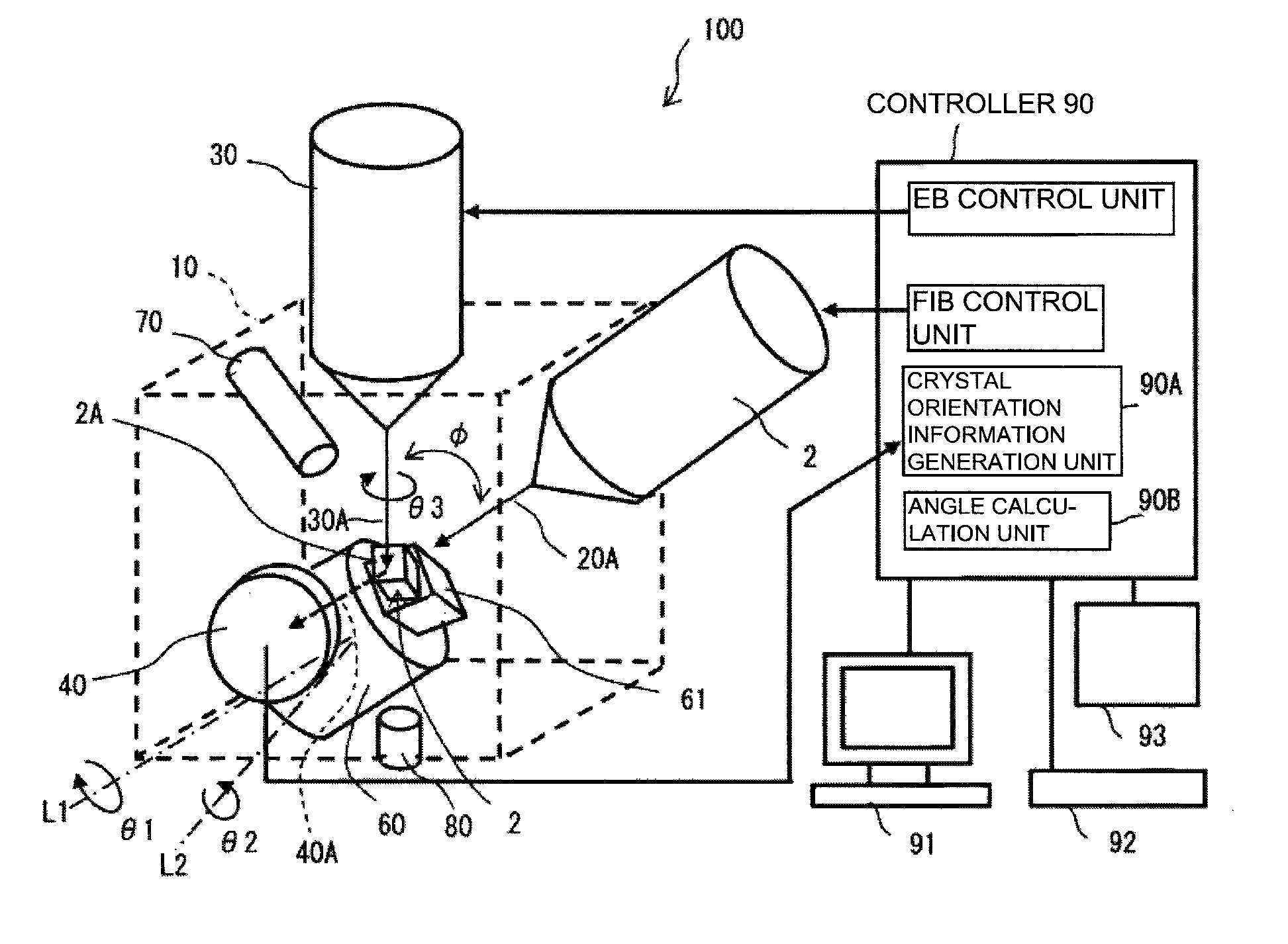
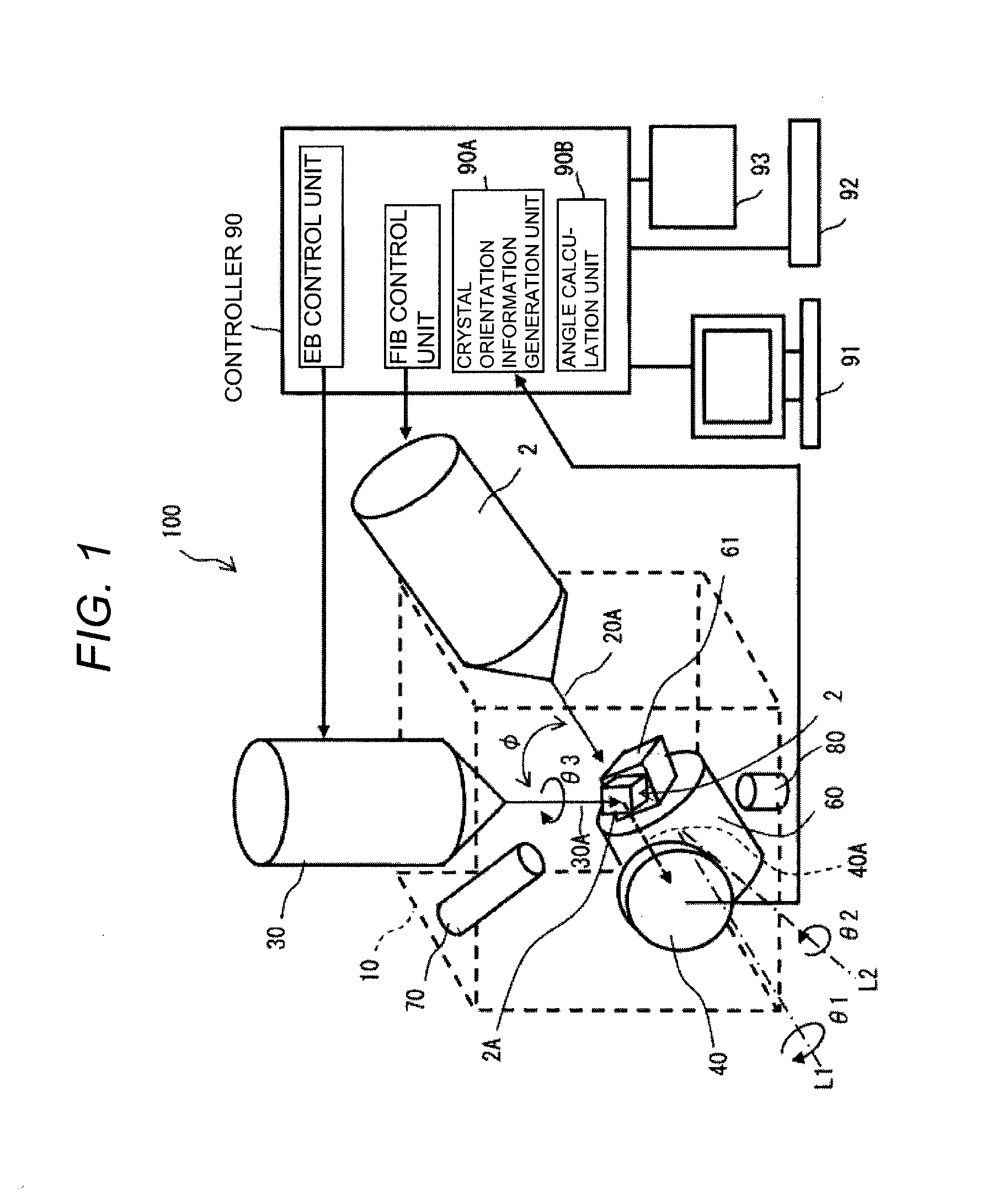
[0024]FIG. 1 is a block diagram illustrating an entire configuration of a charged particle beam apparatus 100 according to an illustrative embodiment of the present invention. In FIG. 1, the charged particle beam apparatus 100 includes a vacuum chamber 10; an ion beam irradiation system (one example of a focused ion beam column) 20 configured to perform irradiation with focused ion beams 20A; an electron beam irradiation system (one example of an electron beam column) 30 configured to perform irradiation with electron beams 30A; a scattered electron detector 40; a sample stage 60 configured to support a sample 2; a secondary charged particle detector 70; a transmitted electron detector 80; and a controller 90. The inside of the vacuum chamber 10 is decompressed to a predetermined vacuum degree, and some or all of the constituent elements of the charged particle bea...


PUM


Abstract

A charged particle beam apparatus includes a sample stage, a focused ion beam column, a scattered electron detector that detects backscattered electrons generated from a cross-section of a sample, a crystal orientation information generation unit that generates crystal orientation information on a predetermined region of the cross-section, and an angle calculation unit that calculates attachment angles of the sample stage, corresponding to a direction of the cross-section. In response to receiving input of information indicating that the crystal orientation information on the region displayed on a display unit is changed to aimed second crystal orientation information, the angle calculation unit calculates the attachment angles corresponding to the direction of the cross-section for generating the second crystal orientation information, and the focused ion beam column performs etching processing on the cross-section at the calculated attachment angles.

Description

[0001]This application claims priority from Japanese Patent Application No. 2013-067319 filed on Mar. 27, 2013, the entire subject-matter of which is incorporated herein by reference.BACKGROUND[0002]1. Technical Field[0003]The disclosure relates to a charged particle beam apparatus which irradiates a sample with electron beams so as to detect emitted backscattered electrons and acquires a diffraction image (EBSD image), a sample processing method using the charged particle beam apparatus, and a sample processing computer program using the charged particle beam apparatus.[0004]2. Description of the Related Art[0005]One of scanning electron microscopes, which focuses electron beams, scans a sample surface with the electron beams so as to detect generated secondary electrons and obtain a secondary electron image, and measures an electron back-scatter diffraction (EBSD) image by using a detector detecting backscattered electrons, is available in the market. By the use of the microscope,...

Claims


Application Information

Patent Timeline
Patent Type & Authority Patents(United States)
IPC IPC(8): H01J37/252H01J37/26H01J37/30
CPCH01J37/3002H01J37/26H01J37/252H01J37/304H01J37/3056H01J2237/30455
Inventor MAN, XINUEMOTO, ATSUSHIASAHATA, TATSUYA
Owner HITACHI HIGH TECH SCI CORP
Why Eureka
Try Eureka