Synchronous light pen electronic whiteboard system

a technology of electronic whiteboard and light pen, applied in the field of electronic whiteboard system, can solve the problems of high power consumption, limited effect of filtering, battery draining quickly,

Inactive Publication Date: 2015-12-08
NANJING FANGRUI TECH
View PDF5 Cites 0 Cited by
  • Summary
  • Abstract
  • Description
  • Claims
  • Application Information

AI Technical Summary

Benefits of technology

[0006]When the solutions of the present invention are adopted, the power consumption of the optical pen can be decreased, the power supply time prolonged and the SNR of the system increased effectively, improving the product's properties greatly, so the practical value of the present invention can be known.

Problems solved by technology

However there is a limit in the effect of using filters since light disturbance is still liable to occur under a certain luminance of the optical pen with possible strong ambient light and in addition, if the light-emitting power is increased too much, the power consumption will be high and the battery will be quickly drained.

Method used


Image

  • Synchronous light pen electronic whiteboard system
  • Synchronous light pen electronic whiteboard system
  • Synchronous light pen electronic whiteboard system

Examples


Embodiment Construction

[0012]Further description about the present invention is made based on the following attached figures and examples.

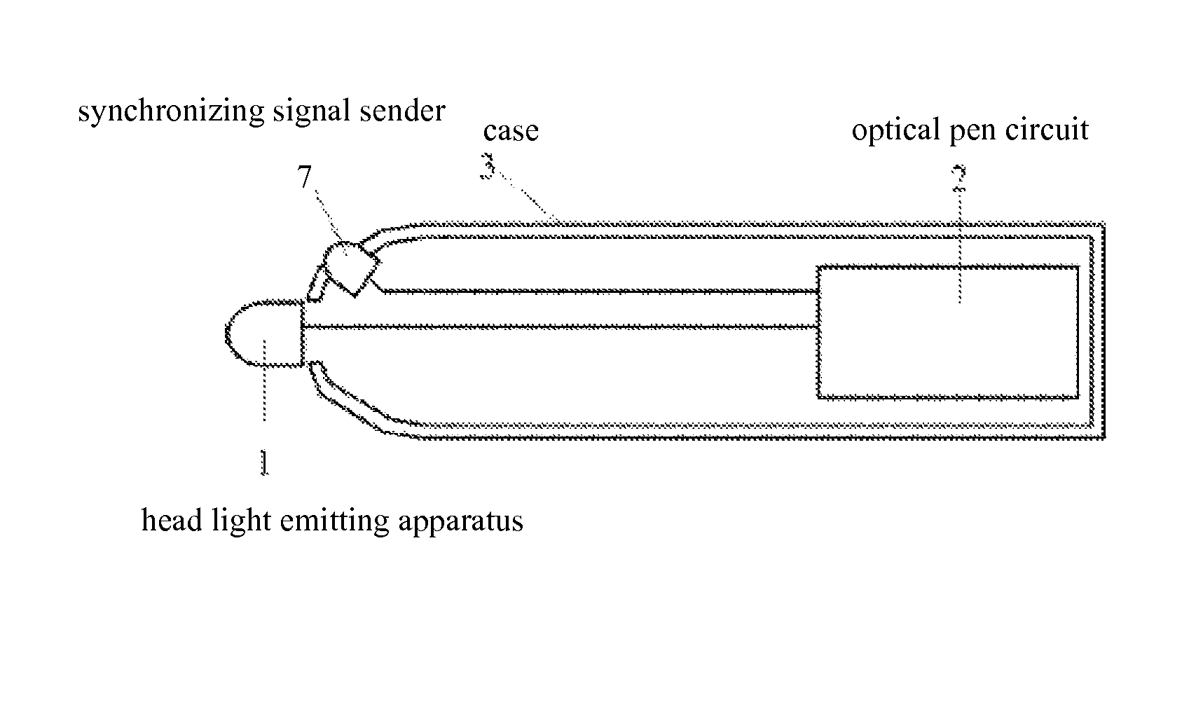
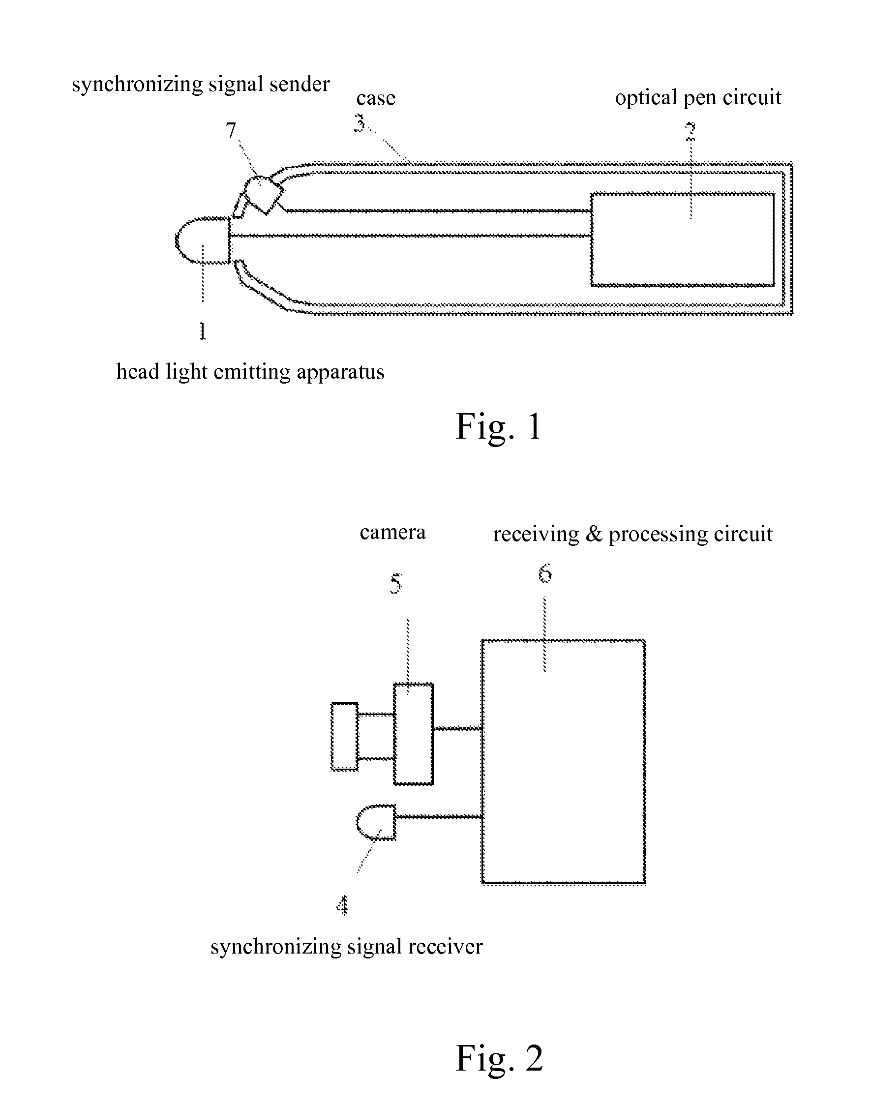
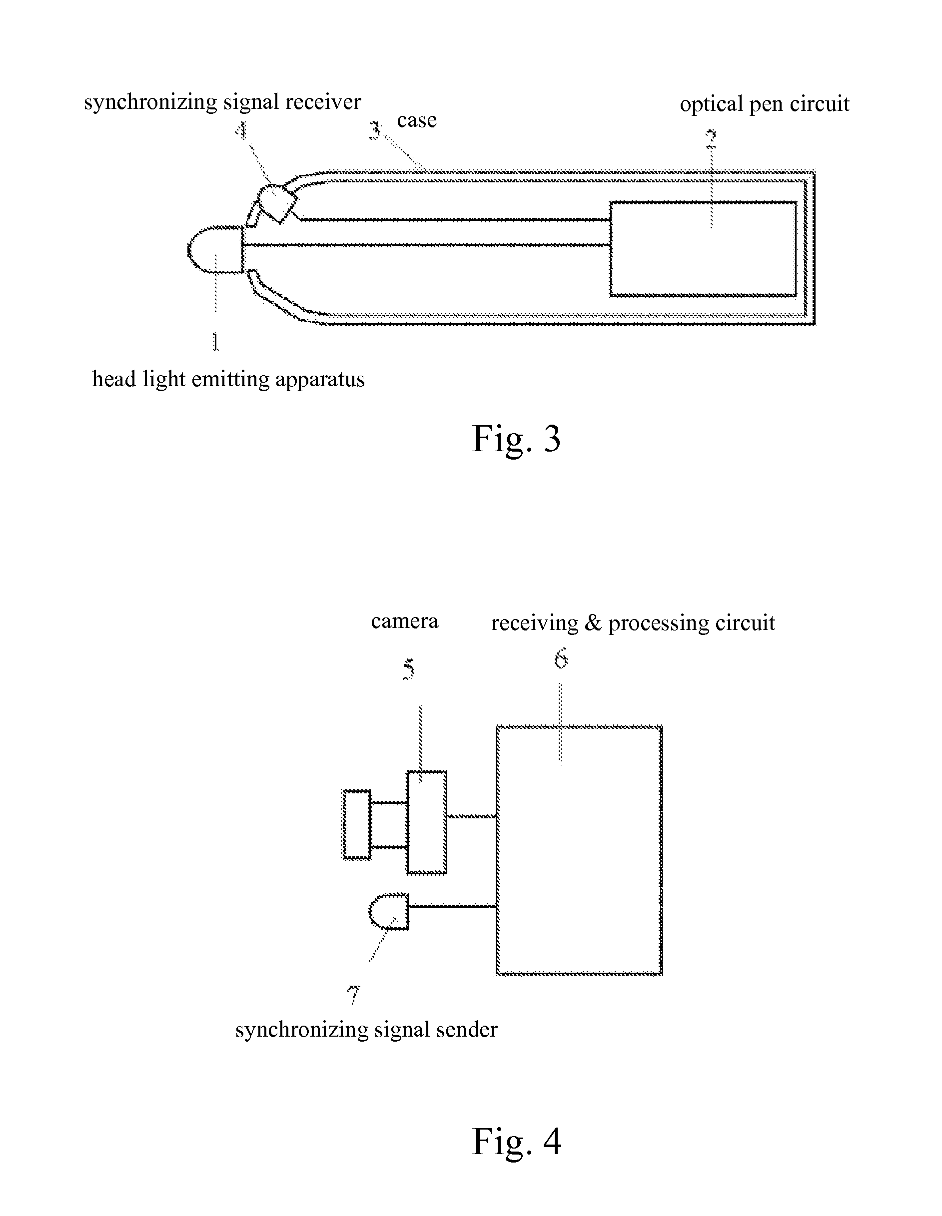
[0013]Both FIGS. 1 and 2 show the embodiment of the structural representation for the synchronous optical pen electronic whiteboard system of the present invention. The head light emitting apparatus (1) is an IR emitting tube that is set on the pen head and connected to the optical pen circuit (2) in the case (3), which is a common arrangement for current technologies. The optical pen circuit (2) is a circuit that is formed by an MCU core. Under the control of the MCU, when the optical pen emits light, the light-emitting pulse width and period are approx. 5 ms and 20 ms respectively, where each pulse is modulated at the carrier of 38 KHz. The synchronizing signal receiver (4) is a common 38 KHz IR receiving module used for IR remote control, which is connected to the receiving & processing circuit (6). When the light-emitting pulse of a optical pen reaches the said IR r...


PUM


Abstract

The synchronous optical pen electronic whiteboard system in the present invention introduces an image sensor with a global shutter, optical pen pulsing light-emission and synchronizing signal transmitter and receiver. The light pulsing of the optical pen and the exposure of the image sensor coincide by synchronizing signal so as to realize the object of increasing signal-to-noise-ratio. A synchronizing signal sender can be arranged in the optical pen and a synchronizing signal receiver arranged in a signal receiving device, or a synchronizing signal sender can be arranged in the signal receiving device and a synchronizing signal receiver arranged in the optical pen. The coincidence of light pulsing and the exposure can be realized in the two solutions, thereby realizing the object of the present invention. By using the solution of the present invention, the power consumption of the optical pen can be reduced effectively and the signal to noise ratio of the system can be effectively increased in the meanwhile.

Description

TECHNICAL FIELD[0001]The present invention relates to an electronic whiteboard system, specifically a synchronous optical pen electronic whiteboard system adopting optical imaging technology.TECHNICAL BACKGROUND[0002]The electronic whiteboard system adopting optical imaging technology is realized through optical pen position tracking, see the China patent of the “System and Method for Computer Information Input Coordinate & Control” with the patent No. ZL011080477 and patent publication No. CN1305143A for detailed information. The operating principle: the target positions are marked by light spots generated by the optical pen, and a photographic device is adopted to collect images in real time. The signal processing circuit is used to analyze image signals in real time and extract the position information of the light spots, which is input into the computer through the interface circuit and the relative software. The coordinate correction algorithm is applied to perform calibration ...

Claims


Application Information

Patent Timeline
Patent Type & Authority Patents(United States)
IPC IPC(8): G06F3/0354G06F3/042G06F3/038
CPCG06F3/03542G06F3/0386G06F3/0425
Inventor BAO, WEI
Owner NANJING FANGRUI TECH
Why Eureka
Try Eureka