Absolute position-measuring device

a position-measuring device and absolute technology, applied in the direction of electric/magnetic position measurements, instruments, and the details of semiconductor/solid-state devices, can solve the problems of not having the information of position, the use of absolute position-measuring devices remains problematic, and the use of absolute position-measuring devices is not easy to achieve. , to achieve the effect of simple structur

Active Publication Date: 2015-12-15
DR JOHANNES HEIDENHAIN GMBH
View PDF20 Cites 2 Cited by
  • Summary
  • Abstract
  • Description
  • Claims
  • Application Information

AI Technical Summary

Benefits of technology

[0009]Example embodiments of the present invention provide an absolute position-measuring device having a simple structure that is suitable for use in an environment in which it is exposed to ionizing radiation.

Problems solved by technology

Compared to absolute position-measuring devices, incremental position-measuring devices have a simple, robust design, but have the disadvantage that immediately after being switched on, no position information is available, and a reference mark must first be overtraveled by what is referred to as a reference measurement, in order to be able to infer the absolute position.
One technical field in which the use of absolute position-measuring devices is still problematic involves installations or machines which are exposed to ionizing, high-energy radiation or whose field of application requires the use of such radiation.
Absolute position-measuring devices, on the other hand, which require a more complex design in order to ascertain an absolute position value, are inclined to break down when they are exposed to ionizing, high-energy radiation.
Both approaches are unsatisfactory in practice.
In order to attain sufficient shielding effect, a centimeter-thick lead casing is necessary, which is undesirable chiefly because of its weight, but also because of its significant space requirement.
Compared to standard components, radiation-hardened components are usually extremely expensive and are only available in large housings.
Therefore, to construct an absolute position-measuring device from radiation-hardened components would result in a large construction and a very high price.
In addition, not all components needed or desired are available in radiation-hardened form.

Method used


Image

  • Absolute position-measuring device
  • Absolute position-measuring device
  • Absolute position-measuring device

Examples


Embodiment Construction

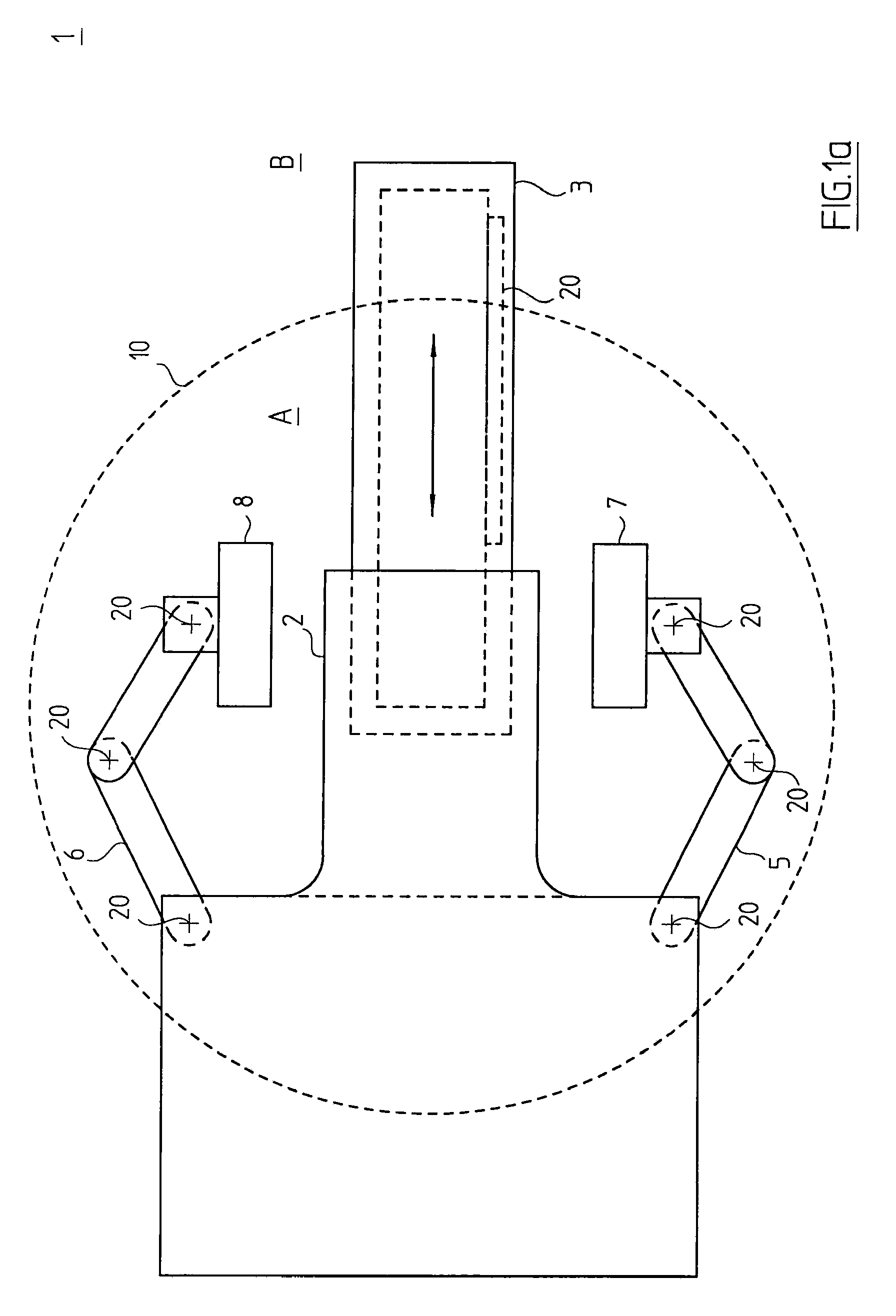
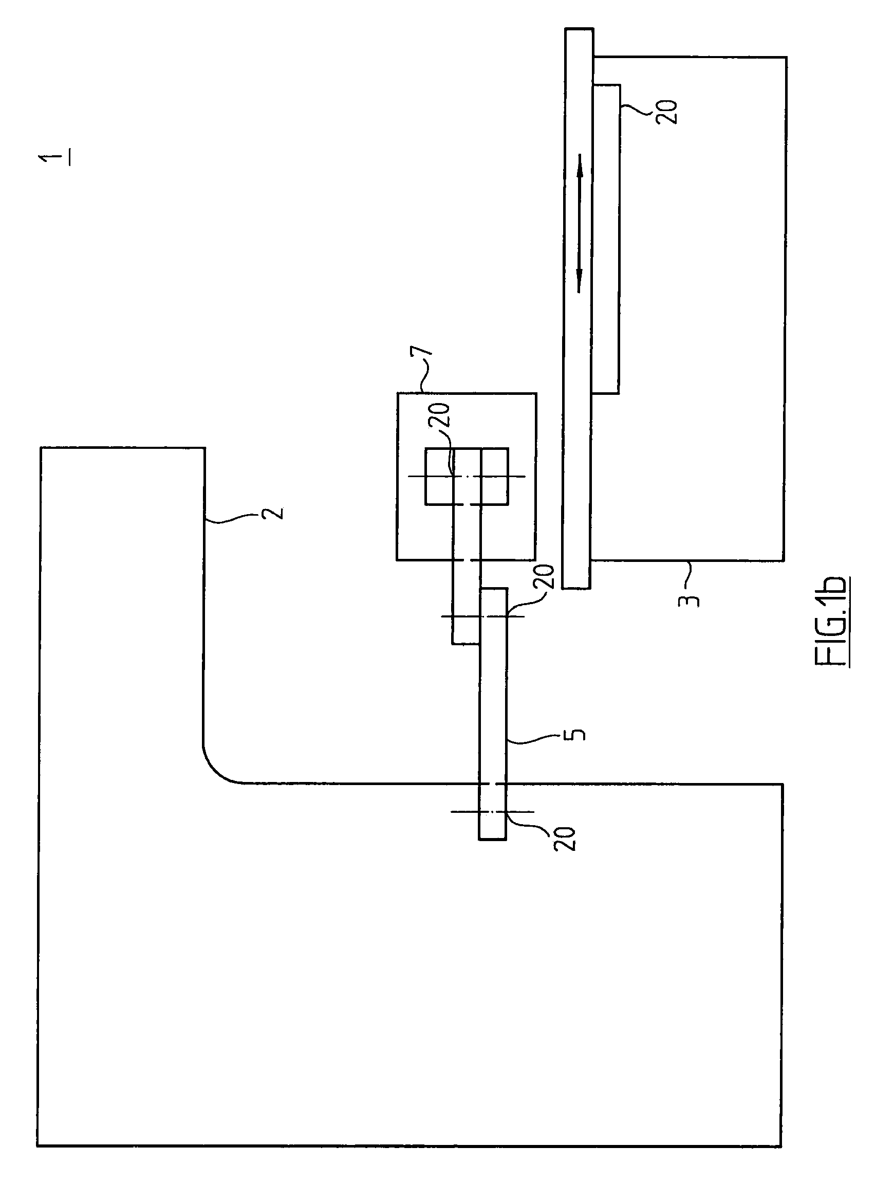
[0016]FIG. 1a is a schematic plan view and FIG. 1b is a schematic side view of a medical irradiation device 1 as example for an installation in which ionizing, high-energy radiation, especially gamma radiation, X-rays or electron radiation, is used. A radiation source 2 of irradiation device 1 is located above the marked head end of a patient examination table 3. For clarity, a detailed representation of the radiation source is not included. It is assumed that the ionizing, high-energy radiation, which is used to irradiate a tumor, for example, can occur predominantly within circle 10 shown in FIG. 1a. Therefore, the area within circle 10 is referred to below as radiation area A. Outside of radiation area A, and thus outside of circle 10, is a radiation-proof area B.

[0017]This division is greatly simplified and is used primarily for the purpose of describing example embodiments of the present invention. The energy of the radiation that occurs decreases with increasing distance from ...


PUM


Abstract

An absolute position-measuring device includes a first subassembly having a measuring standard on which at least one code track is disposed, and a scanning unit with which, by scanning the at least one code track in a measuring direction, position signals are able to be produced, from which an absolute digital position value is able to be generated. The position-measuring device includes a second subassembly having at least one peripheral unit adapted to perform an additional or auxiliary function of the position-measuring device. The first subassembly and the second subassembly are connected to each other by a plurality of electric lines for the transmission of electrical signals. The first subassembly exclusively includes components which are suitable for use in a radiation area of a machine.

Description

CROSS-REFERENCE TO RELATED APPLICATIONS[0001]The present application claims priority to Application No. 10 2012 218 890.8, filed in the Federal Republic of Germany on Oct. 17, 2012, which is expressly incorporated herein in its entirety by reference thereto.FIELD OF THE INVENTION[0002]The present invention relates to an absolute position-measuring device. An absolute position-measuring device of this type is capable of being used in installations or machines in which it is exposed to high-energy ionizing radiation.BACKGROUND INFORMATION[0003]Position-measuring devices are needed in many different technical fields in order to determine the position (length or / and angle) of movable components in installations and machines. Such position-measuring devices are divided into two groups based on their operating principle. First of all, there are incremental, position-measuring devices in which the position is ascertained based on the counting of graduation periods of an incremental graduat...

Claims


Application Information

Patent Timeline
Patent Type & Authority Patents(United States)
IPC IPC(8): G01B7/00H01L23/552G01D5/347G01D3/08
CPCG01B7/003G01D3/08G01D5/34776H01L23/552H01L2224/48137H01L2224/49175G01D5/24461G01D5/34794H01L2924/00
Inventor AUER, DANIELBRATZDRUM, ERWIN
Owner DR JOHANNES HEIDENHAIN GMBH
Why Eureka
Try Eureka