Lever mechanisms for anti-phase mode isolation in MEMS tuning-fork structures

a technology of phase mode isolation and latch mechanism, which is applied in the direction of speed measurement using gyroscopic effects, turn-sensitive devices, instruments, etc., can solve the problems of less likely to be excited, force within the beam to produce a positive frequency drift with increasing temperature, etc., to reduce energy transfer, reduce g-sensitivity, and create a large frequency separation

Active Publication Date: 2015-12-22
RGT UNIV OF CALIFORNIA
View PDF9 Cites 20 Cited by
  • Summary
  • Abstract
  • Description
  • Claims
  • Application Information

AI Technical Summary

Benefits of technology

[0006]The illustrated embodiments feature two design structures for use in high-Q MEMS tuning fork resonators, as well as any tuning-fork device utilizing an anti-phase resonance for other purpose, such as reduction of g-sensitivity. These structures are able to stiffen and dampen the in-phase tuning fork resonance mode while leaving the high-Q anti-phase resonance mode compliant. This feature effectively raises the in-phase resonance frequency, and potentially creates a large frequency separation between the two resonance modes. The primary benefit of these structures is to reduce energy transfer between the two modes, allowing a higher robustness to external acceleration. The large frequency separation alone offers an advantage towards this effect. However, because the in-phase mode is of a higher frequency which is not typical in most environments, this mode is even less likely to be excited for most applications. The reduction of external energy transfer to the modes of interest is important for high-Q structures, as even if a small amount of energy is transferred to the high-Q mode, this energy will continue to oscillate within the mode and disturb sensitive measurements.
[0007]The two designs which have been implemented to produce this effect include first one that can be placed between the two resonance tuning fork tines and a second that can be wrapped around the structure. While both have been shown to increase the frequency separation of the two resonance modes, the internal levering mechanism has the added benefit of requiring less space and potentially being applied to quadruple mass devices. This has an additional benefit for gyroscopes by reducing quadrature between the two modes of resonance. These designs can also be used to create FM accelerometers with large, non-linear mechanical scale factors by placing the in- and anti-phase resonances close together.
[0008]An additional benefit of the design is potential frequency robustness to temperature through proper design and fabrication of the structure. Most silicon resonators exhibit a negative frequency drift with increasing temperature due to the softening of the Young's Modulus. Because the primary stiffness of the discussed design structures is contributed from a clamped-clamped beam, mismatch in the thermal expansion coefficients between the material of the device and the substrate can induce force within the beam to produce a positive frequency drift with increasing temperature. Combining the two effects with proper design can produce at least first-order temperature drift cancellation.

Problems solved by technology

However, because the in-phase mode is of a higher frequency which is not typical in most environments, this mode is even less likely to be excited for most applications.
Because the primary stiffness of the discussed design structures is contributed from a clamped-clamped beam, mismatch in the thermal expansion coefficients between the material of the device and the substrate can induce force within the beam to produce a positive frequency drift with increasing temperature.

Method used


Image

  • Lever mechanisms for anti-phase mode isolation in MEMS tuning-fork structures
  • Lever mechanisms for anti-phase mode isolation in MEMS tuning-fork structures
  • Lever mechanisms for anti-phase mode isolation in MEMS tuning-fork structures

Examples


Embodiment Construction

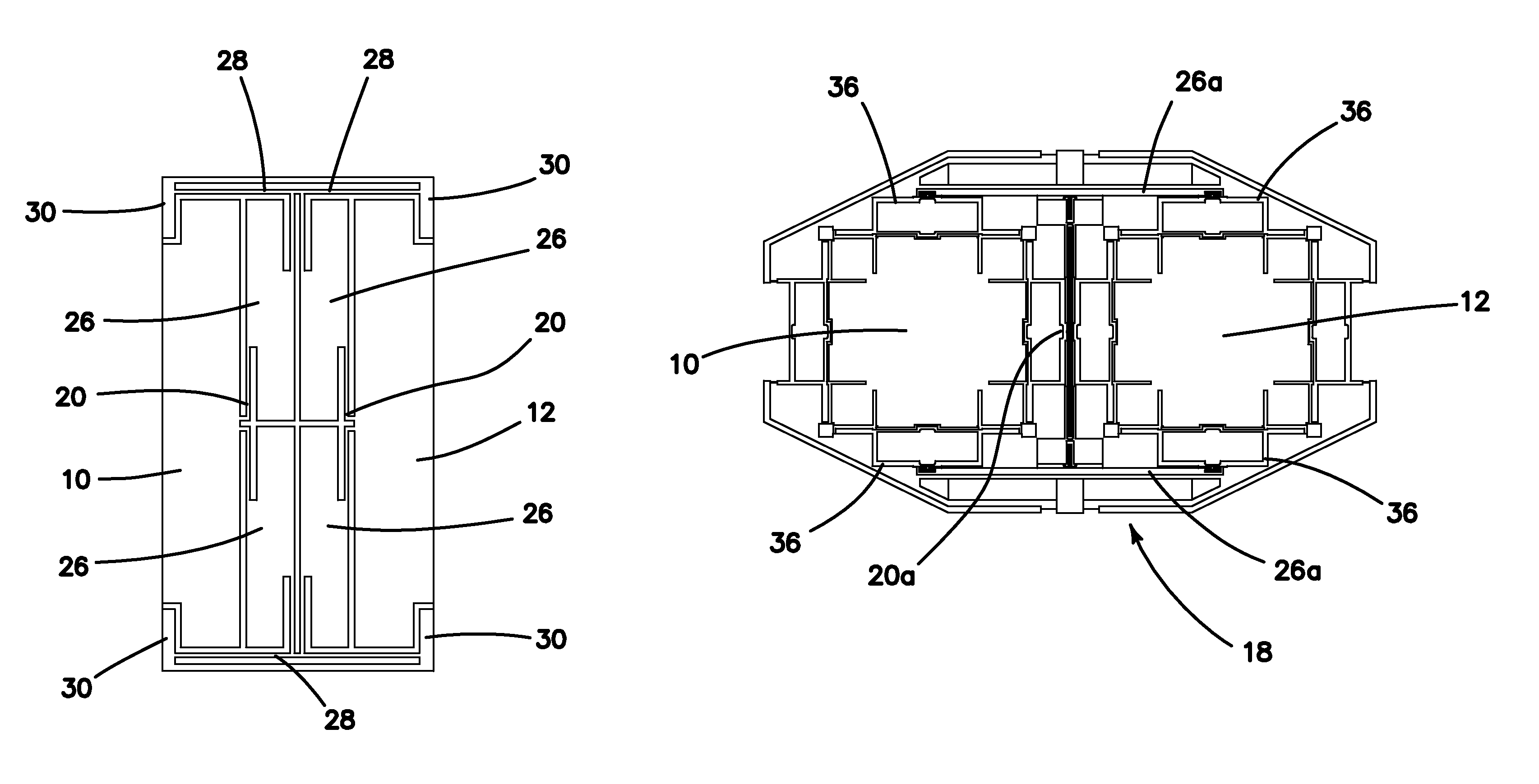
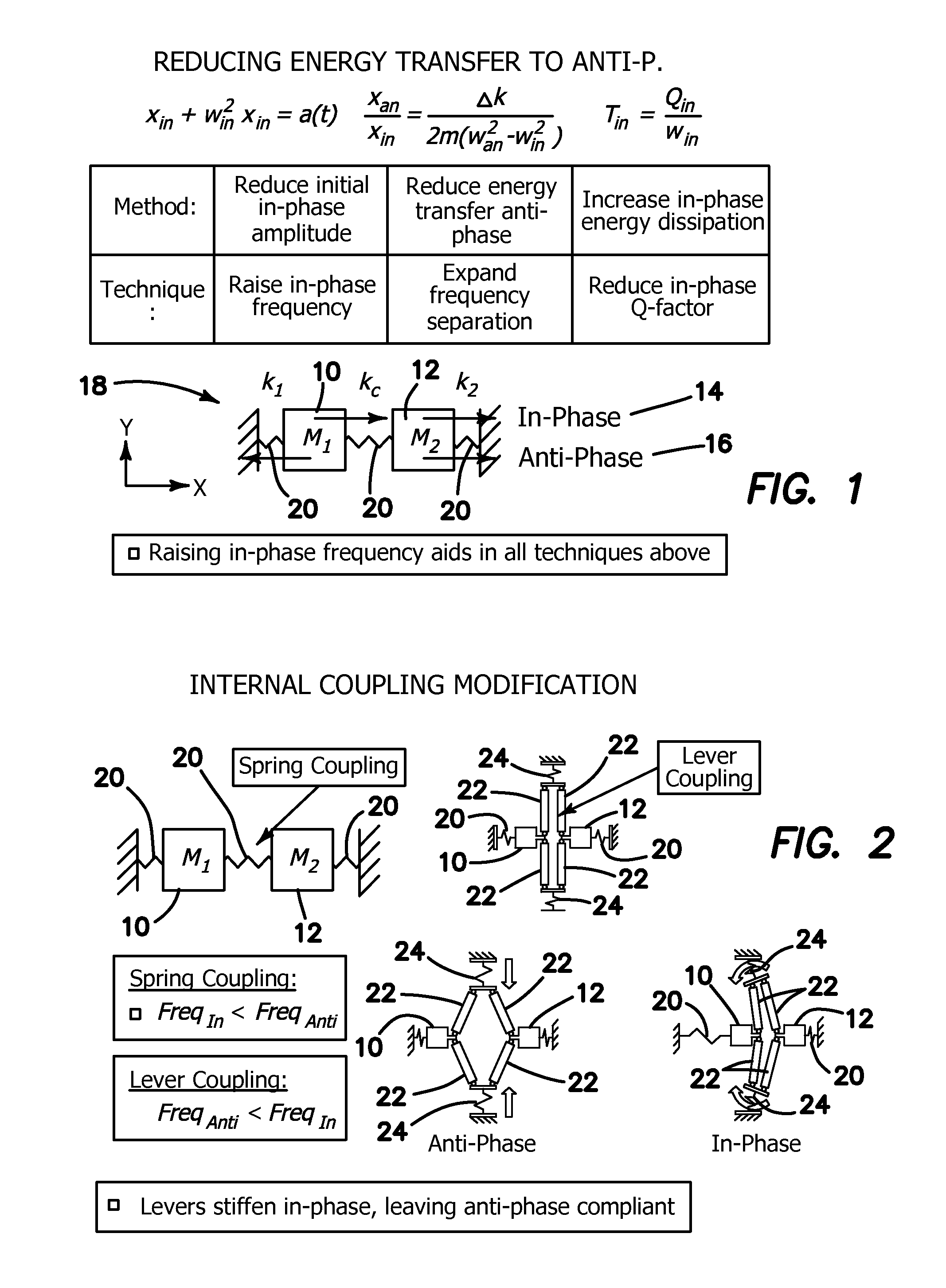
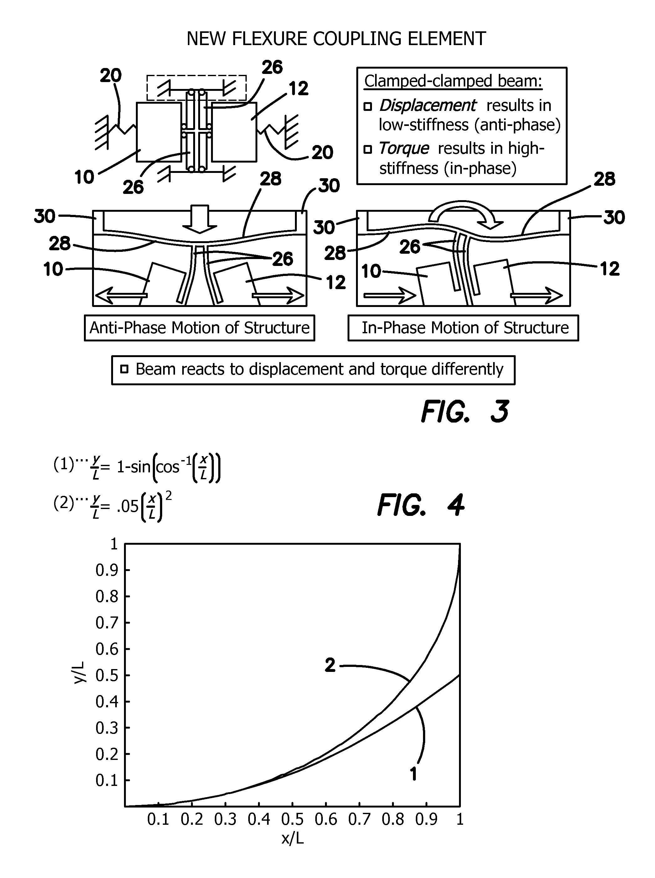
[0050]The illustrated embodiments of the invention improve the design of tuning-fork structures. Generally speaking, tuning-forks are symmetric resonators that are operated using anti-phase motion. They consist of at least two masses or tines 10, 12, and are each driven independently with equal magnitude and opposite directional force as shown in FIG. 1. These masses or tines 10, 12 inherently have more than one mode of resonance, namely an anti-phase mode 16, as well as an in-phase mode 14, where both masses 10, 12 displace in the same direction. It is the in-phase mode 14, which we attempt to avoid with the anti-phase resonance because it is sensitive to external acceleration, and dissipates energy through the anchors of the structure (not shown) due to unbalanced linear momentum, thus lowering Q-factor. Both of these effects are avoided with an ideal anti-phase motion. These types of masses or tines 10, 12 are commonly used for many types of vibratory MEMS devices, including reso...


PUM


Abstract

A MEMS resonator includes two resonating masses having an anti-phase and in-phase resonance mode, each mode having a resonance frequency, and an anti-phase resonance levering system coupled to the two resonating masses to stiffen and / or dampen the in-phase resonance mode while leaving the anti-phase resonance mode compliant. This effectively raises the in-phase resonance frequency above the anti-phase resonance frequency, and potentially creates a large frequency separation between the two resonance modes. This reduces the energy transfer between the two modes, allowing for robustness to external acceleration, because the in-phase mode is of a higher frequency. The anti-phase resonance levering system is disposed between the two resonating masses as an internal levering mechanism, or is disposed around the two resonating masses as an external levering mechanism.

Description

GOVERNMENT RIGHTS[0001]This invention was made with government support under N00014-09-1-0424 awarded by National Institutes of Health. The government has certain rights in the invention.BACKGROUND[0002]1. Field of the Technology[0003]The disclosure relates to the field of micromachined inertial sensors, tuning fork architecture, resonators, gyroscopes, and accelerometers.[0004]2. Description of the Prior Art[0005]Quality factor is a important characteristic for the performance of many types of mechanical resonators employed as sensors. With the consideration of micromachined vibratory gyroscopes and rate-integrating gyroscopes, maximizing the quality factor increases sensitivity to external rotation and reduction of the signal-to-noise ratio. One method of increasing the quality factor for these types of devices is through the use of multiple-mass resonators operating in anti-phase vibratory modes. These types of resonators offer larger quality factors by balancing the linear and a...

Claims


Application Information

Patent Timeline
Patent Type & Authority Patents(United States)
IPC IPC(8): G01C19/56H03H9/24G01C19/5621G01P15/097H03H9/02
CPCG01P15/097G01C19/5621H03H9/2468H03H9/2463H03H2009/02496
Inventor SIMON, BRENTON R.TRUSOV, ALEXANDER A.SHKEL, ANDREI M.
Owner RGT UNIV OF CALIFORNIA
Why Eureka
Try Eureka