Particulate matter purifying material, filter catalyst for purifying particulate matter using particulate matter purifying material, and method of regenerating filter catalyst for purifying particulate matter

a technology of filter catalyst and particulate matter, which is applied in the direction of metal/metal-oxide/metal-hydroxide catalyst, machine/engine, etc., can solve the problems of affecting the effect of catalyst powder and temperature increase, so as to promote the effect of increasing the temperature and reducing the catalyst

Active Publication Date: 2015-12-29
NISSAN MOTOR CO LTD
View PDF34 Cites 0 Cited by
  • Summary
  • Abstract
  • Description
  • Claims
  • Application Information

AI Technical Summary

Benefits of technology

[0020]The present invention has been made in view of such conventional problems. It is an object of the present invention to provide a particulate matter purifying material that has an excellent PM purifying property and is capable of starting purifying PM at a low temperature and preventing thermal runaway in a filter catalyst, a filter catalyst for purifying particulate matter using the particulate matter purifying material, and a method of regenerating the filter catalyst for purifying the particulate matter.

Problems solved by technology

Therefore, when a large amount of PM is deposited, the deposited PM is burned in a self chain reaction mode, and an excessive increase in temperature is thus promoted.
As a result, a problem of a decrease of the catalyst effect may be caused.
Namely, since the PM and the catalyst powder are both solid in the actual filter, it is difficult to enhance a rate of contact between the PM and the catalyst powder.
Thus, it is not unclear whether the effect of the improvement of the low temperature activation can be achieved sufficiently.
Therefore, there is a problem to cause thermal degradation of the catalysts since the burning control is difficult.
In addition, there is a possibility that the PM may not be burned completely depending on the PM deposition distribution on the filter.
Further, even though a catalyst material having an excellent activation property at a low temperature is used, a rate of contact between the PM and the catalyst material that are both solid is low when these are supported on an actual filter, and the sufficient action thereof cannot be achieved.
As a result, the conventional problems such as a decrease in fuel consumption and thermal runaway of the filter catalyst still remain.

Method used


Image

  • Particulate matter purifying material, filter catalyst for purifying particulate matter using particulate matter purifying material, and method of regenerating filter catalyst for purifying particulate matter
  • Particulate matter purifying material, filter catalyst for purifying particulate matter using particulate matter purifying material, and method of regenerating filter catalyst for purifying particulate matter
  • Particulate matter purifying material, filter catalyst for purifying particulate matter using particulate matter purifying material, and method of regenerating filter catalyst for purifying particulate matter

Examples


examples

[0078]The following is a further specific explanation of the present embodiment with reference to examples. However, the scope of the present invention is not limited to these examples.

[Manufacture of Filter Catalyst 1]

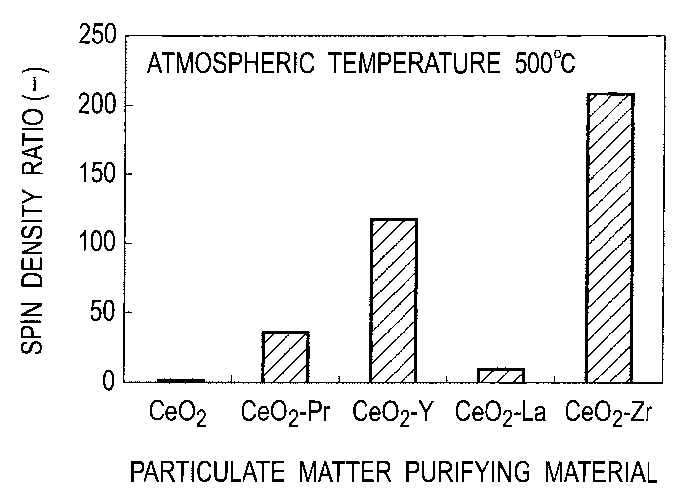
[0079](Manufacture of Particulate Matter Purifying Material (CeO2—Pr))

[0080]First, cerium nitrate and praseodymium nitrate were dissolved in ion-exchanged water in such a manner that an atomic ratio of cerium to praseodymium was 7:3, so as to prepare a mixed aqueous solution. Next, diluted ammonia water was added to the mixed aqueous solution, followed by stirring, so as to obtain a coprecipitated substance. Then, the coprecipitated substance was filtered, washed with water, dried and baked, thereby preparing a CeO2—Pr composite oxide.

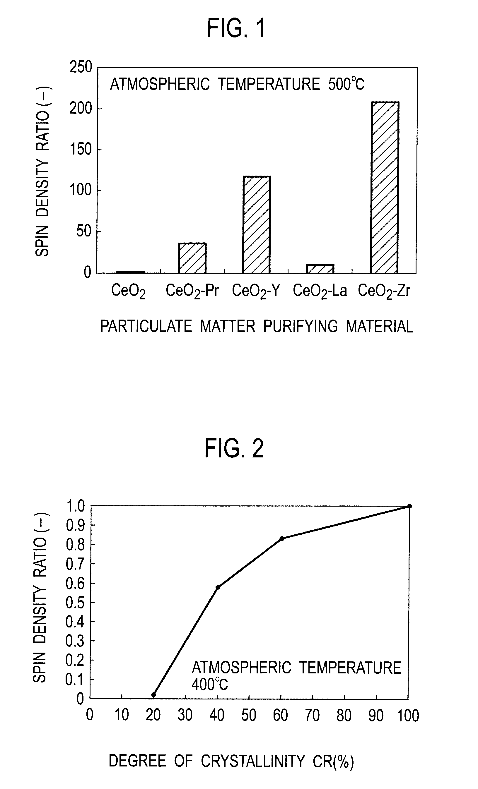
[0081]Then, powder of the CeO2—Pr composite oxide (Ce:Pr=7:3 (atomic ratio)) was baked in an electric furnace in air for five hours while varying temperatures, so as to obtain seven types of powders 1 to 7, each having different degree o...


PUM

PropertyMeasurementUnit
degree of crystallinityaaaaaaaaaa
crystallite diameteraaaaaaaaaa
specific surface areaaaaaaaaaaa

Abstract

A particulate matter purifying material is used for a filter catalyst for purifying particulate matter that is disposed in an exhaust gas flow path of an internal combustion engine, traps the particulate matter in exhaust gas generated in the internal combustion engine, and burns the particulate matter to be deposited, so as to be regenerated. The particulate matter purifying material includes an oxide containing cerium (Ce) having an oxygen storage-release capacity, and at least one metal (Me) selected from the group consisting of Zr, Y, La, Pr, Sr, Nb and Nd, wherein a content ratio (Ce:Me) of cerium to the metal is 6:4 to 9:1 in terms of an atomic ratio, and a degree of crystallinity (CR) represented by the following formula (1) is within a range of 25 to 60%:Degree of crystallinity (CR)=I / I0×100(%)  (1)wherein I represents an X-ray diffraction peak intensity with regard to a (111) plane of a CeO2 phase in the particulate matter purifying material, and I0 represents the X-ray diffraction peak intensity with regard to the (111) plane of the CeO2 phase after the particulate matter purifying material is baked in air at 1000° C.

Description

TECHNICAL FIELD[0001]The present invention relates to a particulate matter purifying material capable of purifying, with high efficiency, particulate matter included in exhaust gas from an internal combustion engine driving under a lean burn condition, relates to a filter catalyst for purifying particulate matter using the particulate matter purifying material, and further relates to a method of regenerating a filter catalyst for purifying particulate matter.BACKGROUND ART[0002]In recent years, in consideration of a global environment, a reduction in carbon dioxide (CO2) emissions has been highly desired. Therefore, enhancements of a lean burn operation are being made in order to achieve better fuel consumption of an internal combustion engine of a vehicle.[0003]Exhaust gas emitted from a lean-burn gasoline engine, a direct-injection engine or a diesel engine contains a lot of oxygen. Thus, a conventional three-way catalyst can hardly reduce and purify nitrogen oxide (NOx). Further,...

Claims


Application Information

Patent Timeline
Patent Type & Authority Patents(United States)
IPC IPC(8): F01N3/00B01D53/94B01D46/00B01D46/24C01F17/00B01J23/00B01J23/10B01J23/20B01J23/63B01J23/648B01J23/66F01N3/022F01N3/02B01J35/00B01J35/04B01J37/03B01J35/10C01F17/235C01F17/241
CPCF01N3/0222B01D46/0061C01F17/0043B01J23/66B01J23/6484B01J23/63B01J23/20B01J23/10B01J23/002B01D53/944B01D46/2418Y02T10/20C01P2006/12C01P2004/61C01P2004/52C01P2002/74B01J2523/00B01J37/03B01J35/1014B01J35/04B01J35/002B01D2258/012B01D2255/908B01D2255/40B01D2255/206B01J2523/3712B01J2523/48B01J2523/824B01J2523/24B01J2523/828B01J2523/36B01J2523/18B01J2523/3706B01J2523/3725B01J2523/56Y02P20/584Y02T10/12C01F17/241C01F17/235B01D46/82
Inventor AKAMA, HIROSHIONODERA, HITOSHINISHIZAWA, TORUHANAKI, YASUNARIMORISAKA, HIDEAKI
Owner NISSAN MOTOR CO LTD
Why Eureka
Try Eureka