Coke plant including exhaust gas sharing

a technology of coke plant and exhaust gas, applied in the field of coke plants, can solve problems such as air tight environmen

Active Publication Date: 2016-01-26
SUNCOKE TECH & DEV LLC
View PDF246 Cites 48 Cited by
  • Summary
  • Abstract
  • Description
  • Claims
  • Application Information

AI Technical Summary

Problems solved by technology

Both oven types are typically constructed of refractory bricks and other materials in which creating a substantially airtight environment can be a challenge because small cracks can form in these structures during day-to-day operation.

Method used


Image

  • Coke plant including exhaust gas sharing
  • Coke plant including exhaust gas sharing
  • Coke plant including exhaust gas sharing

Examples


Embodiment Construction

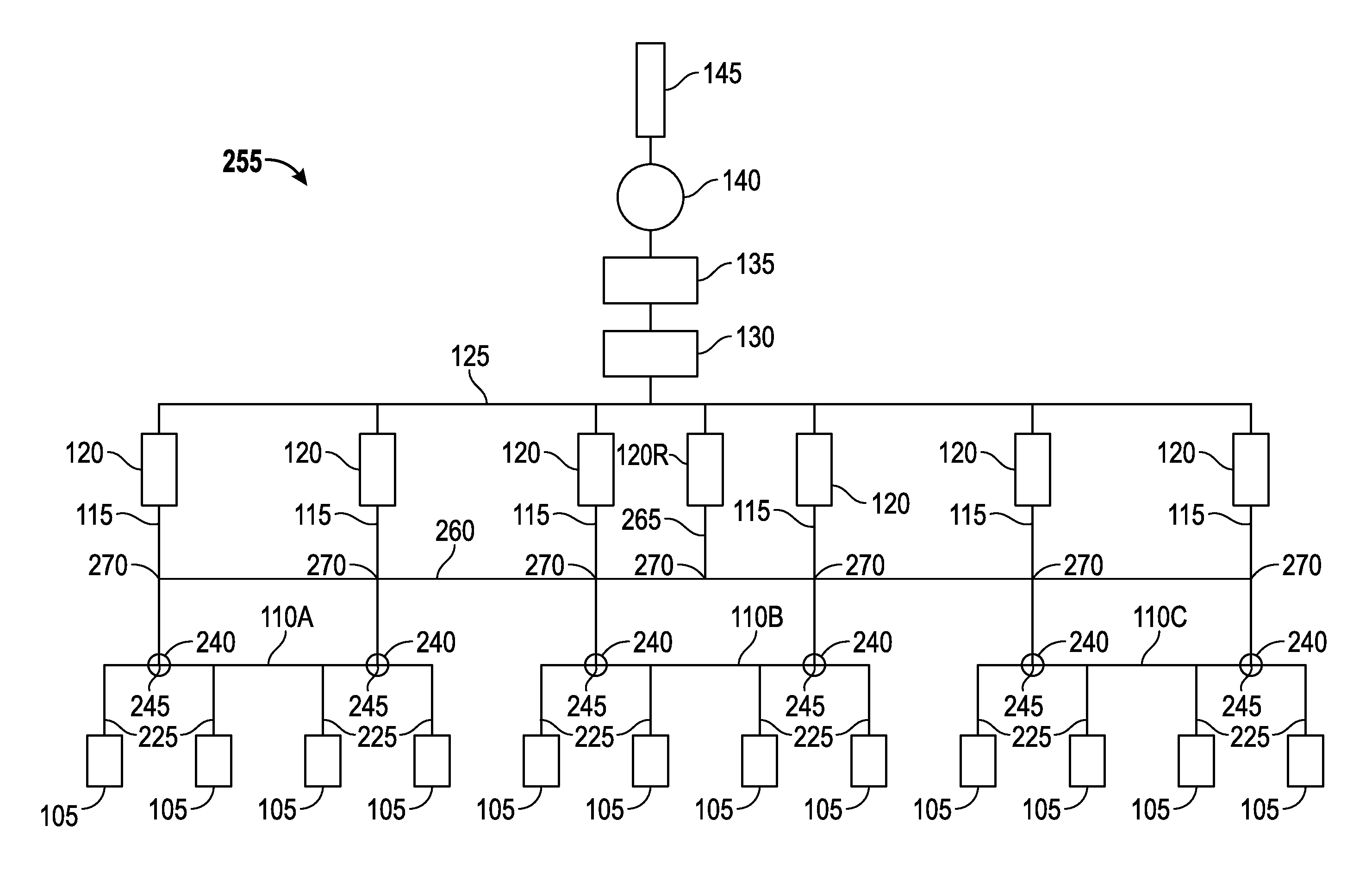
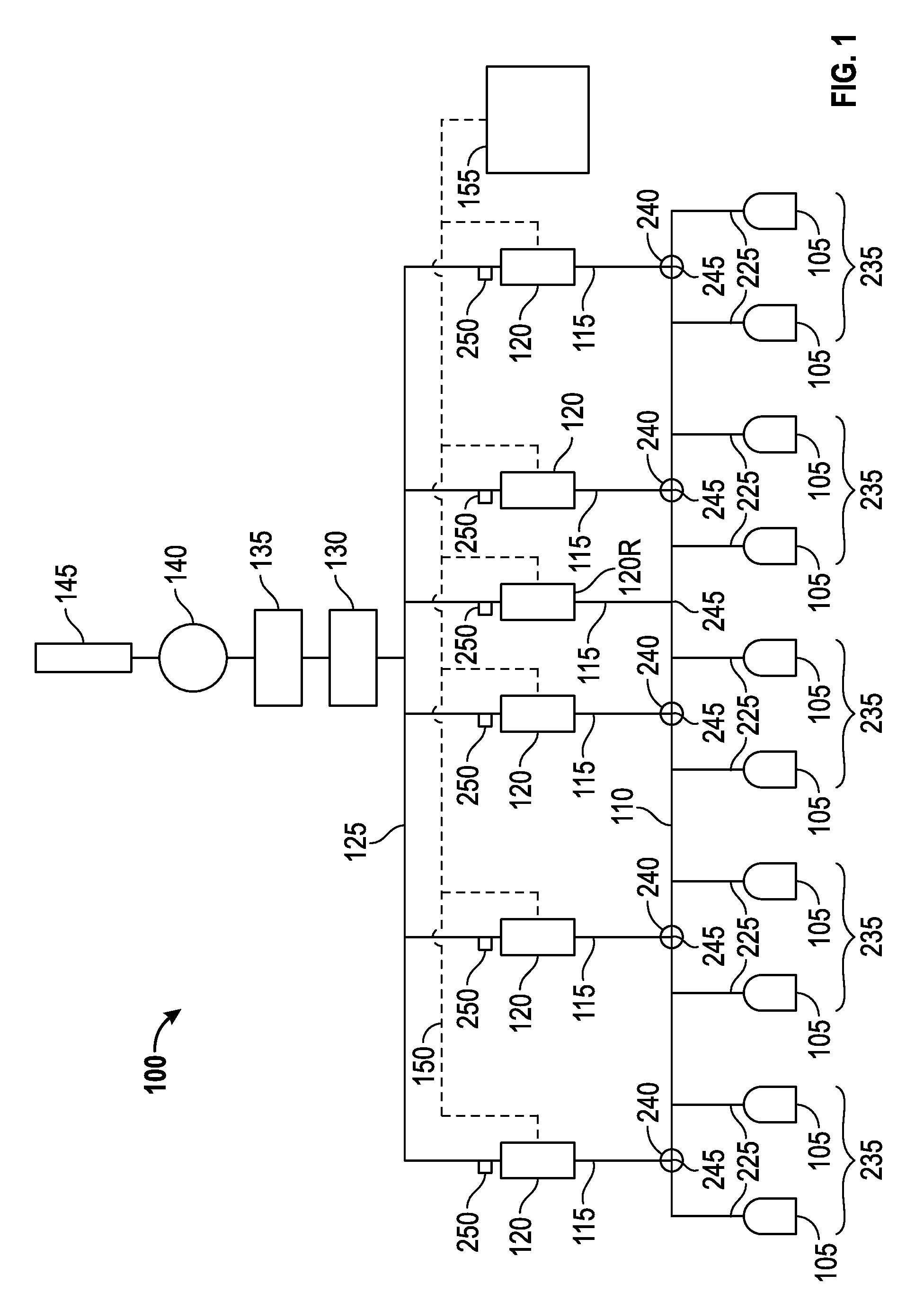
[0014]Referring to FIG. 1, a HHR coke plant 100 is illustrated which produces coke from coal in a reducing environment. In general, the HHR coke plant 100 comprises at least one oven 105, along with heat recovery steam generators (HRSGs) 120 and an air quality control system 130 (e.g. an exhaust or flue gas desulfurization (FGD) system) both of which are positioned fluidly downstream from the ovens and both of which are fluidly connected to the ovens by suitable ducts. The HHR coke plant 100 preferably includes a plurality of ovens 105 and a common tunnel 110 fluidly connecting each of the ovens 105 to a plurality of HRSGs 120. One or more crossover ducts 115 fluidly connects the common tunnel 110 to the HRSGs 120. A cooled gas duct 125 transports the cooled gas from the HRSG to the flue gas desulfurization (FGD) system 130. Fluidly connected and further downstream are a baghouse 135 for collecting particulates, at least one draft fan 140 for controlling air pressure within the syst...


PUM

PropertyMeasurementUnit
inner diameteraaaaaaaaaa
flow velocitiesaaaaaaaaaa

Abstract

A coke plant includes multiple coke ovens where each coke oven is adapted to produce exhaust gases, a common tunnel fluidly connected to the plurality of coke ovens and configured to receive the exhaust gases from each of the coke ovens, multiple standard heat recovery steam generators fluidly connected to the common tunnel where the ratio of coke ovens to standard heat recovery steam generators is at least 20:1, and a redundant heat recovery steam generator fluidly connected to the common tunnel where any one of the plurality of standard heat recovery steam generators and the redundant heat recovery steam generator is adapted to receive the exhaust gases from the plurality of ovens and extract heat from the exhaust gases and where the standard heat recovery steam generators and the redundant heat recovery steam generator are all connected in parallel with each other.

Description

BACKGROUND OF THE INVENTION[0001]The present invention relates generally to the field of coke plants for producing coke from coal. Coke is an important raw material used to make steel. Coke is produced by driving off the volatile fraction of coal, which is typically about 25% of the mass. Hot exhaust gases generated by the coke making process are ideally recaptured and used to generate electricity. One style of coke oven which is suited to recover these hot exhaust gases are Horizontal Heat Recovery (HHR) ovens which have a unique environmental advantage over chemical byproduct ovens based upon the relative operating atmospheric pressure conditions inside the oven. HHR ovens operate under negative pressure whereas chemical byproduct ovens operate at a slightly positive atmospheric pressure. Both oven types are typically constructed of refractory bricks and other materials in which creating a substantially airtight environment can be a challenge because small cracks can form in these...

Claims


Application Information

Patent Timeline
Patent Type & Authority Patents(United States)
IPC IPC(8): C10B15/02F22B1/18C10B45/00C10B5/04C10B49/02C10B5/00C10B5/08C10B5/06C10B5/02
CPCC10B15/02C10B45/00F22B1/18C10B5/00C10B5/02C10B5/04C10B5/06C10B5/08C10B49/02Y02P20/129C10B5/12C10B41/00
Inventor QUANCI, JOHN F.CHUN, PETER U.KAPLAREVIC, MILOS J.REILING, VINCE G.
Owner SUNCOKE TECH & DEV LLC
Why Eureka
Try Eureka