
Method for reducing mechanical stress on at least one component of the drive train of a motor vehicle, and corresponding motor vehicle

a technology of mechanical drive train and component, which is applied in the direction of braking system, electric devices, braking components, etc., can solve the problems of premature wear, extreme stress on mechanical drive train, excite vibration on the articulated shaft, etc., and achieve the effect of reducing the risk of damage to the components of the drive train

Active Publication Date: 2016-02-09
AUDI AG
View PDF25 Cites 0 Cited by
  • Summary
  • Abstract
  • Description
  • Claims
  • Application Information

AI Technical Summary

Benefits of technology

The present invention aims to reduce damage to components of the motor vehicle's drive train and increase safety for occupants. The invention achieves this by reducing mechanical stresses on the articulated shaft and optional additional gear stage, resulting in smaller dimensions and cost savings. The elasticity of the articulated shaft produces resonance frequencies that can cause discomfort to occupants and impair ABS control. The invention reduces these resonances to improve the motor vehicle's comfort and safety. The mechanical stress of the articulated shaft due to contact force between the wheel and the road surface can be minimized by compensating the moments of inertia of the electric machine. The electric machine associated with the drive wheel can be controlled in the same direction as the friction brake to reduce torsional moments and torsional vibrations.

Problems solved by technology

With ABS control or with full braking without ABS control, these moments of inertia can cause extreme stress on the mechanical drive train, especially on an articulated shaft connecting an electric machine and an associated drive wheel as well as an optional additional gear stage.
This mechanical stress can cause damage, especially premature wear.
Moreover, the aforementioned moments of inertia in conjunction with an elastic articulated shaft can excite vibrations on the articulated shaft due to the dynamic ABS interventions on the friction brake.
These vibrations can also lead to premature wear of the drive shafts as well as of an optional additional gear stage.

Method used


Image

  • Method for reducing mechanical stress on at least one component of the drive train of a motor vehicle, and corresponding motor vehicle
  • Method for reducing mechanical stress on at least one component of the drive train of a motor vehicle, and corresponding motor vehicle
  • Method for reducing mechanical stress on at least one component of the drive train of a motor vehicle, and corresponding motor vehicle

Examples


Embodiment Construction

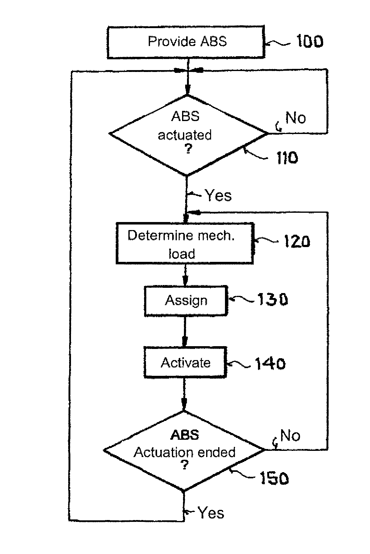
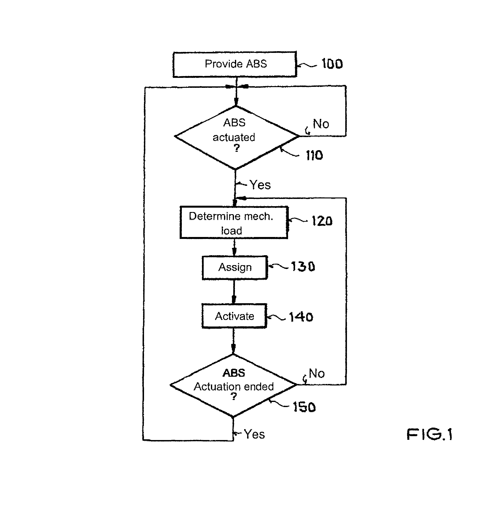
[0025]FIG. 1 shows a schematic diagram of a flow diagram of an exemplary embodiment of a method according to the invention. First, at step 100, an anti-lock braking system acting separately on the friction brakes of each individual wheel of the motor vehicle is provided. Subsequently, at step110, it is checked whether the anti-lock braking system has been actuated. If this is the case, then step 120 is executed, wherein mechanical stress of at least one articulated shaft connecting the electric machine and an associated drive wheel is determined. Thereafter, at step 130, at least one cause for the determined mechanical stress is assigned to the at least one drive wheel. In step 140, the electric machine associated with the drive wheel is controlled so as to counteract the cause for the mechanical stress associated with the drive wheel is counteracted, wherein the stress is especially minimized or even compensated. It is then checked at step 150 whether the ABS actuation has been ter...


PUM


Abstract

In a method for reducing a mechanical stress of a component of a drive train of a motor vehicle with at least two wheels, of which at least one wheel is a drive wheel, wherein the motor vehicle has an anti-lock braking system and an electric machine which is coupled to the drive wheel, wherein each wheel of the motor vehicle has a dedicated friction brake, the anti-lock braking system operates individually on each friction brake. During activation of the anti-lock braking system, mechanical stress of an articulated shaft connecting the electric machine and the coupled drive wheel is determined, and the electric machine coupled to the drive wheel is controlled so as to counteract the mechanical stress. A motor vehicle making use of the method si also disclosed.

Description

CROSS-REFERENCES TO RELATED APPLICATIONS[0001]This application is the U.S. National Stage of International Application No. PCT / EP2012 / 003344, filed Aug. 4, 2012, which designated the United States and has been published as International Publication No. WO 2013 / 041167 and which claims the priority of German Patent Application, Serial No. 10 2011 114 303.7, filed Sep. 23, 2011, pursuant to 35 U.S.C. 119(a)-(d).BACKGROUND OF THE INVENTION[0002]The present invention relates to a method for reducing mechanical stress on at least one component of the drive train of a motor vehicle having at least two wheels, of which at least one wheel is a drive wheel, wherein the motor vehicle has an anti-lock braking system and at least one electric machine which for driving precisely one drive wheel the motor vehicle is coupled to this drive wheel, and wherein a respective friction brake is associated at least two wheels of the motor vehicle. The present invention further relates to a motor vehicle wi...

Claims


Application Information

Patent Timeline
IPC IPC(8): B60W30/184B60L15/20B60L3/10B60L7/10B60W30/02B60W10/184B60T17/22B60W10/08B60L7/26B60W30/18B60T8/32B60T8/175
CPCB60W10/08B60L3/106B60L3/108B60L7/10B60L7/26B60L15/20B60L15/2009B60T8/175B60T8/32B60T17/22B60W10/184B60W30/02B60W30/1846B60W30/18109B60L2270/145B60T2201/09B60T2270/604B60W2710/083Y02T10/7275Y02T10/64Y02T10/72
Inventor ROSENBERGER, MARTIN
Owner AUDI AG
Learn More