
Systems and methods for providing a convection-enhanced delivery device

a delivery device and convection technology, applied in the field of convection-enhanced delivery systems, can solve the problems of ineffective systemic or intrathecal delivery of drugs, inability to accurately position the catheter within the target tissue, incomplete, etc., and achieve the effects of reducing the vertical profile of the delivery device, and reducing the distance between the adapter portion

Active Publication Date: 2016-03-08
BECTON DICKINSON & CO
View PDF9 Cites 3 Cited by
  • Summary
  • Abstract
  • Description
  • Claims
  • Application Information

AI Technical Summary

Benefits of technology

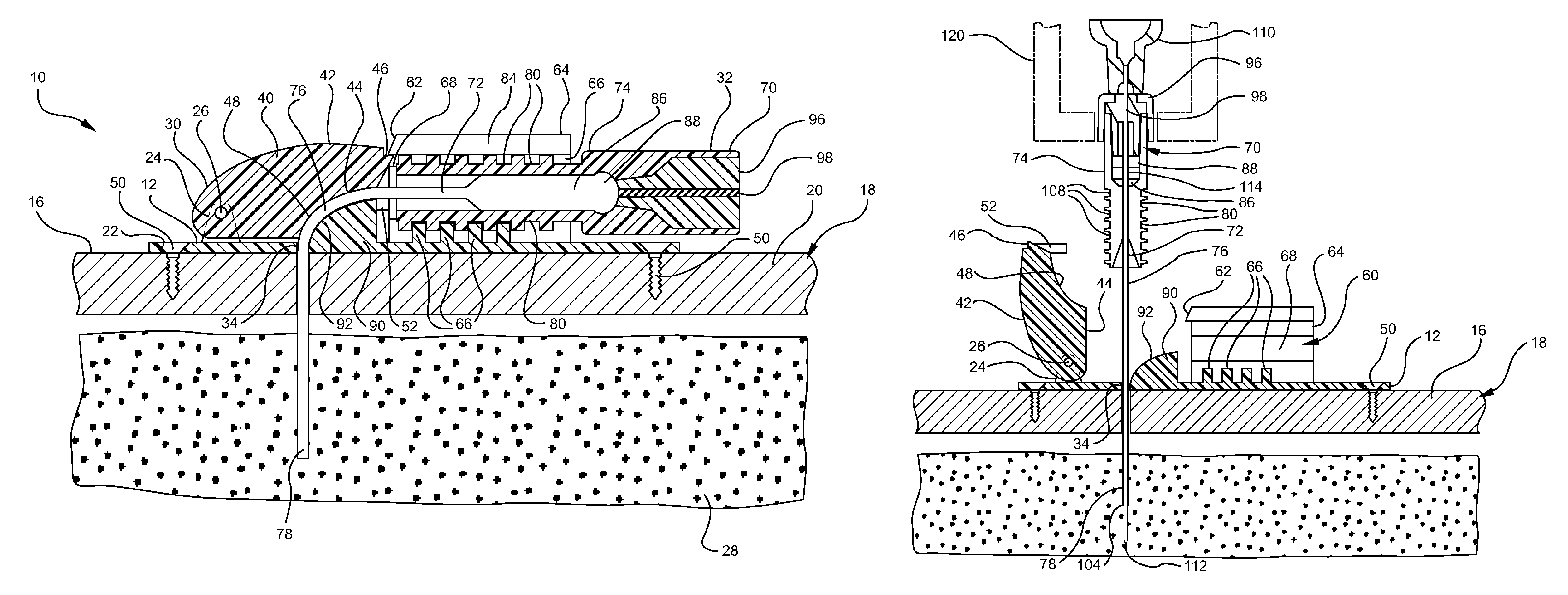
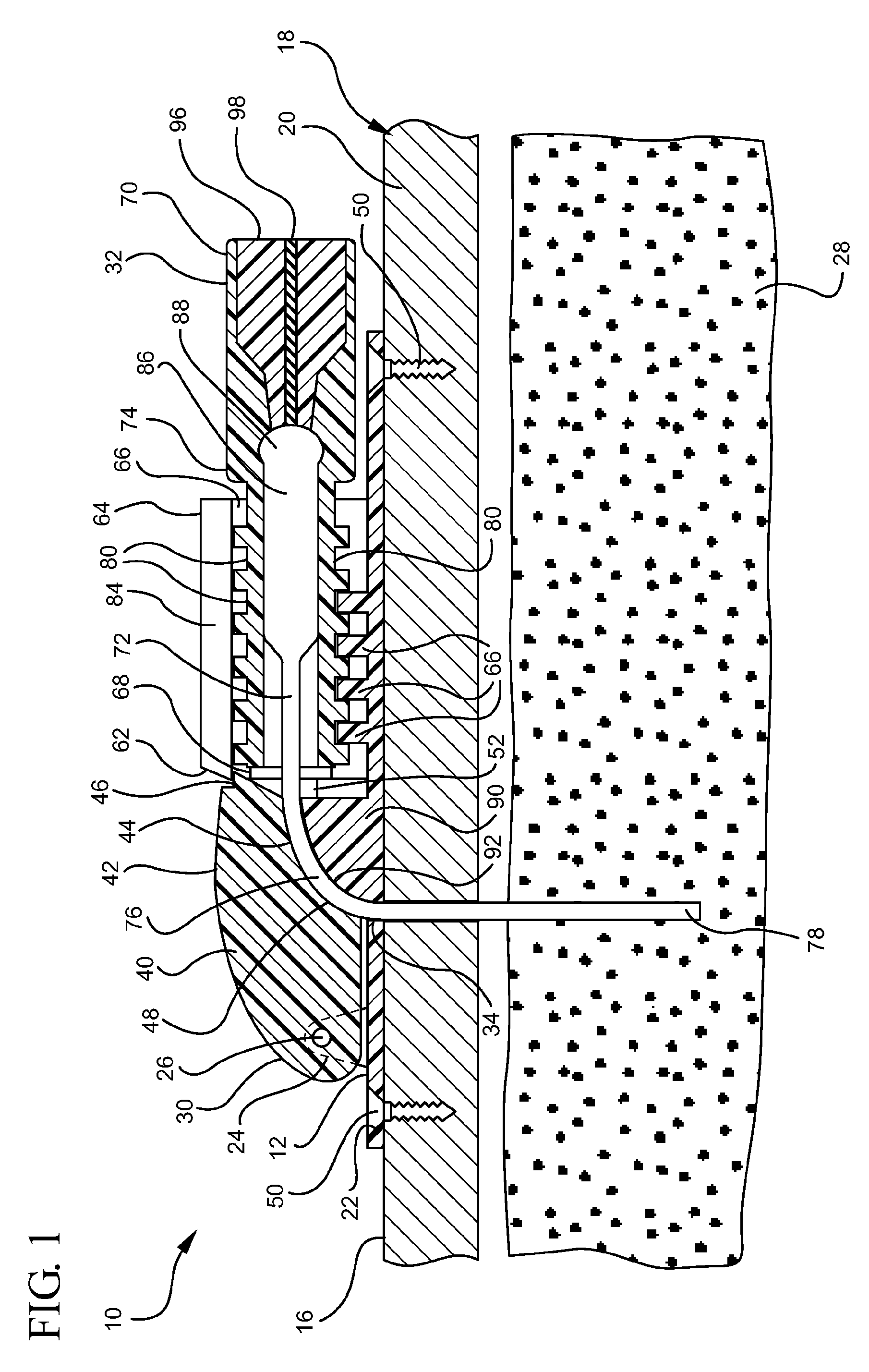
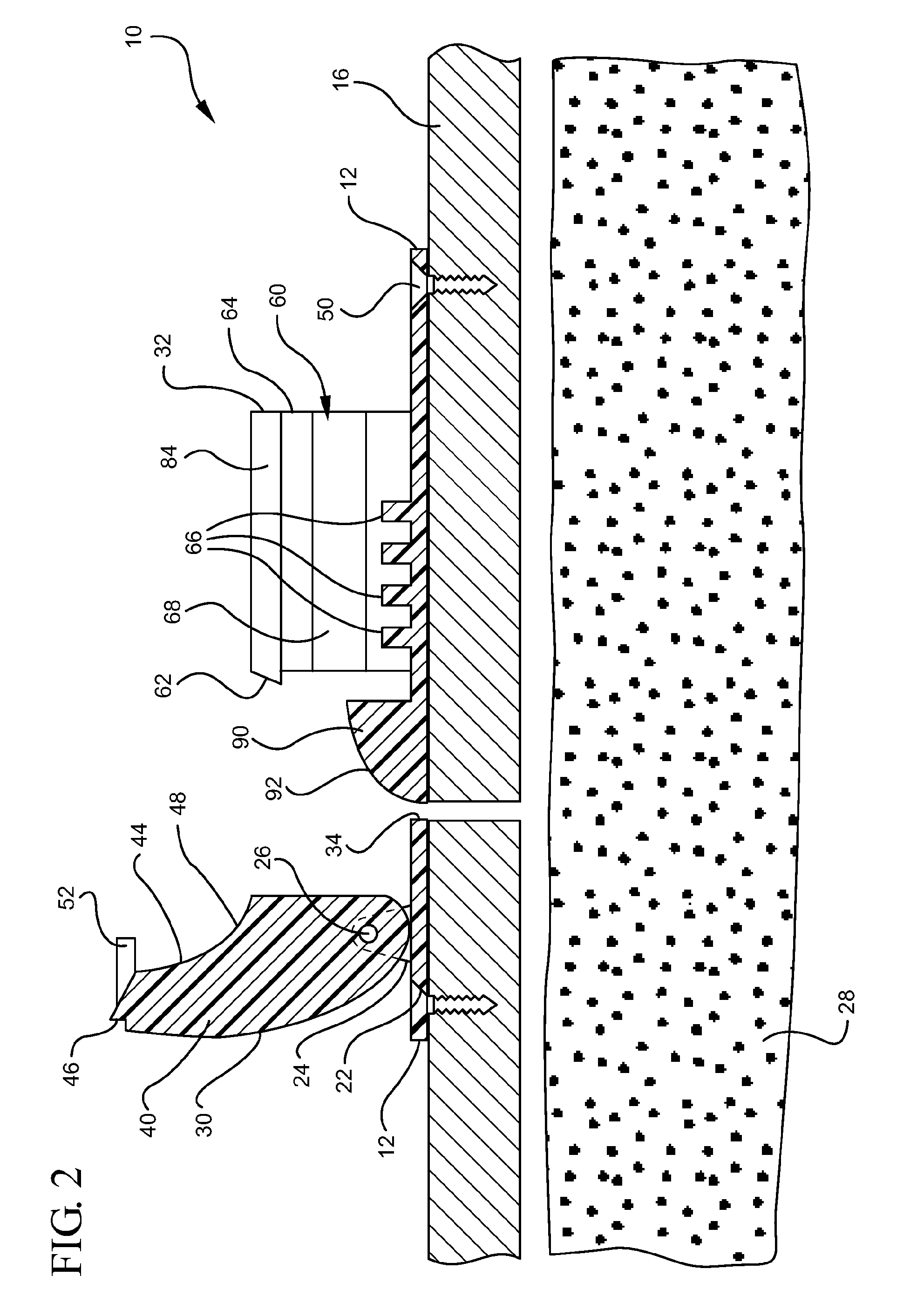
[0006]The base member further includes a hinged clip that selectively moves between an opened position and a closed position. The opened position of the hinged clip exposes the aperture through the base thereby enabling a catheter to be inserted through the aperture and into the target tissue to a desired insertion depth. Once the desired insertion depth is attained, the hinged clip is selectively moved to and locked in a closed position to secure the insertion depth of the catheter in the target tissue. Additionally, the closed position of the hinged clip repositions an adapter portion of the catheter from a vertical orientation to a horizontal orientation. The horizontal orientation reduces the distance between the adapter portion of the catheter and the patient, thereby reducing the vertical profile of the delivery device and inserted catheter.
[0007]The base member further includes a receiving channel for receiving and securing the adapter portion of the catheter when the delivery device is in a closed position. An inner surface of the receiving channel may include features for adjustably interacting with an outer surface of the catheter adapter. For example, in some implementations of the present invention the inner surface of the receiving channel includes a plurality of tongues that fit within a plurality of grooves located on an external surface of the catheter adapter. In other implementations the inner surface of the receiving channel includes a contour or feature that mirrors an external surface of the catheter adapter. The interaction of the receiving channel and the catheter adapter retain the catheter adapter within the receiving channel at various positions within the receiving channel. In some implementations of the present invention, the insertion depth of the catheter in the target tissue is adjusted by selectively positioning the catheter adapter within the receiving channel. In other implementations, compatible features between abutting surfaces of the receiving channel and the catheter adapter enable precise and predetermined insertion depths of the catheter within the target tissue.
[0008]In some embodiments a semi-flexible, metallic catheter is used in conjunction with the delivery device. In other embodiments a flexible, polymer based catheter is used with the delivery device, thereby requiring the use of a trocar or introducer needle to insert the catheter into the target tissue. In some implementations of the present invention, a micromanipulator is coupled to a portion of the catheter adapter to provide control and accuracy for insertion of the catheter into the target tissue.

Problems solved by technology

For example, for central nervous system (CNS) applications, drug delivery by systemic or by intrathecal methods is not very effective because of the blood-brain bather and limitations with regard to the drug diffusion into the tissue.
At best, traditional methods of treatment result in incomplete, non-targeted and heterogeneous dispersion throughout the CNS.
The ability to accurately position the catheter within the target tissue is a difficult challenge requiring precise instrumentation and experienced hands.
However these methods are unsightly and inconvenient for the patient.
Thus, while methods currently exist for maintaining the inserted position of CED catheters, challenges still exist.

Method used


Image

  • Systems and methods for providing a convection-enhanced delivery device
  • Systems and methods for providing a convection-enhanced delivery device
  • Systems and methods for providing a convection-enhanced delivery device

Examples


Embodiment Construction

[0019]The presently preferred embodiments of the present invention will be best understood by reference to the drawings, wherein like reference numbers indicate identical or functionally similar elements. It will be readily understood that the components of the present invention, as generally described and illustrated in the figures herein, could be arranged and designed in a wide variety of different configurations. Thus, the following more detailed description, as represented in the figures, is not intended to limit the scope of the invention as claimed, but is merely representative of presently preferred embodiments of the invention.

[0020]Referring now to FIG. 1, a convection-enhanced delivery system 10 is shown. The delivery system 10 comprises a base 12 that includes a generally planar mounting surface 14 that interfaces directly with an outer surface 16 of a patient 18. In some embodiments, the mounting surface 14 of the base 12 is arched or otherwise shaped to conform to a no...


PUM


Abstract

A delivery device system is provided for assisting a patient and physician in maintaining a depth and position of an inserted catheter within a target tissue. The delivery device includes a base member that is secured to an external surface of the patient. The base member includes an aperture through which a catheter is inserted to access the target tissue. The base member further includes a hinged clip that selectively locks into a closed position to secure the catheter within the delivery device and maintain a desired insertion depth of the catheter within the target tissue. The base member further includes a receiving channel for compatibly and adjustably securing an adapter portion of the catheter in a horizontal orientation.

Description

[0001]This application is a National Stage of International Application No. PCT / US2010 / 020609, filed Jan. 11, 2010, and entitled SYSTEMS AND METHODS FOR PROVIDING A CONVECTION-ENHANCED DELIVERY DEVICE which claims the benefit of U.S. Provisional Application No. 61 / 144,023, filed Jan. 12, 2009. This application claims priority to and incorporates herein by reference the above-referenced applications in their entirety.BACKGROUND OF THE INVENTION[0002]The present invention relates to a convection-enhanced delivery system for use in any targeted drug delivery procedure including convection-enhanced delivery (CED) and chronic intracranial administrations. CED is the continuous injection under positive pressure of a fluid containing a therapeutic agent. This technique is especially useful for administering therapeutic agents to tissues that are inaccessible via traditional oral medications or venous infusion techniques. For example, for central nervous system (CNS) applications, drug deli...

Claims


Application Information

Patent Timeline
Patent Type & Authority Patents(United States)
IPC IPC(8): A61M25/02
CPCA61M25/02A61M2025/024
Inventor HAIDER, M. ISHAQMARTIN, FRANKKLUG, RICHARD
Owner BECTON DICKINSON & CO
Learn More