Device for inductive transmission of electrical energy

a technology of inductive transmission and electrical energy, applied in the direction of transformer/inductance circuit, electric vehicle, inductance, etc., can solve the problems of metal foreign bodies, unsuitable existing safety measures, and insufficient largely automatic operation, so as to improve the operating safety of the inductive energy transmission system.

Active Publication Date: 2016-03-08
CONDUCTIX WAMPFLER
View PDF49 Cites 8 Cited by
  • Summary
  • Abstract
  • Description
  • Claims
  • Application Information

AI Technical Summary

Benefits of technology

[0005]Therefore, the underlying object of the invention is to improve the operating safety of an induc

Problems solved by technology

If objects made of metal materials are introduced into the area of such a field, eddy currents are induced in these which lead to heating dependent on the material, time of exposure and level of field strength.
In the presence of such conditions, such an object can reach a temperature which can lead to damage, e.g. to melting of plastic surfaces, or to hazards to persons.
Due to the characteristics of existing applications for inductive energy transmission systems, such a hazard

Method used


Image

  • Device for inductive transmission of electrical energy
  • Device for inductive transmission of electrical energy
  • Device for inductive transmission of electrical energy

Examples


Embodiment Construction

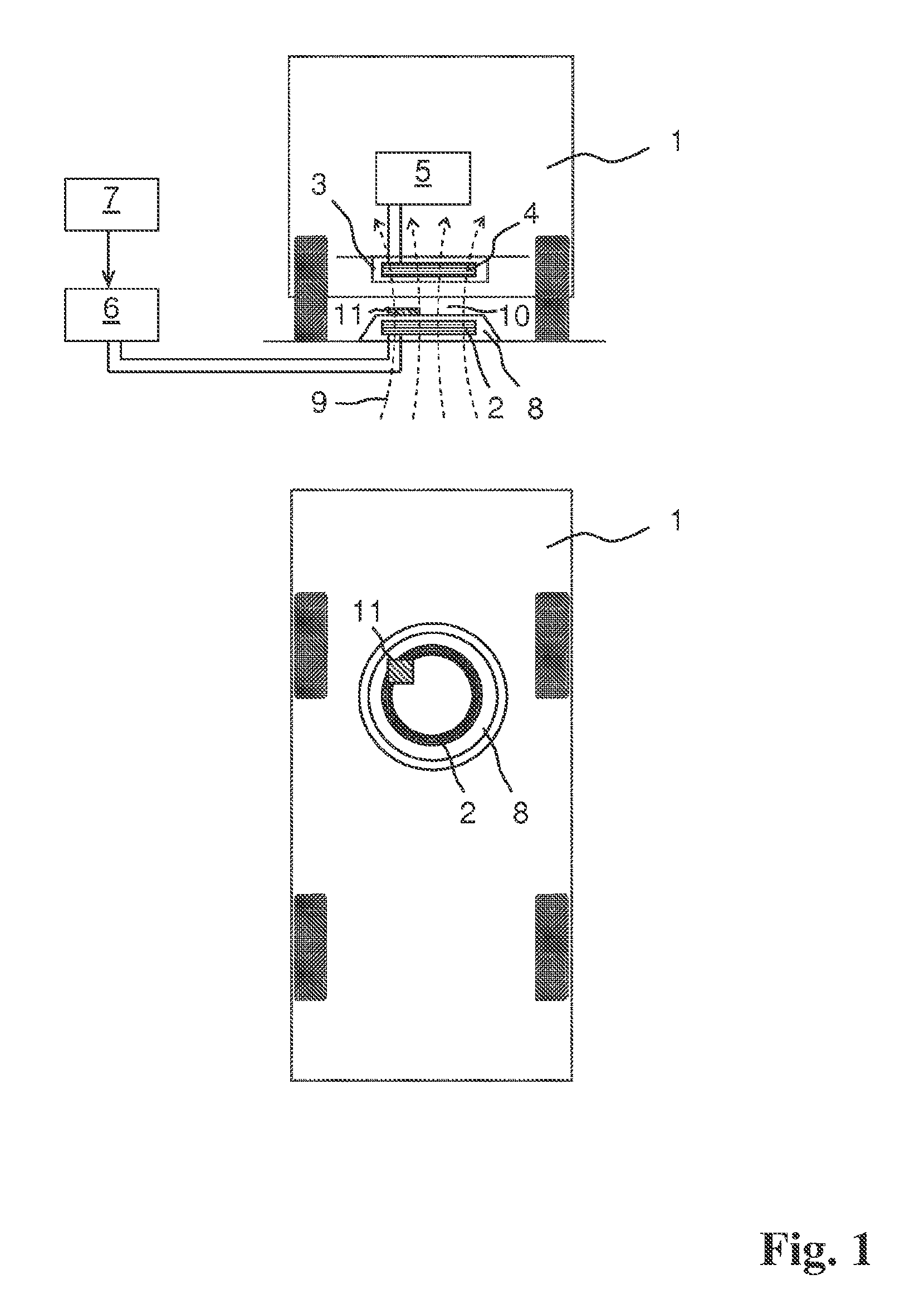
[0012]FIG. 1 shows a diagrammatic sectional view (at the top) and a diagrammatic plan view (at the bottom) of an electric vehicle 1 standing over the primary coil 2 of a charging station to charge its battery. On the underside of the vehicle 1 in a housing 3 there is a secondary coil 4 which is connected to an electronic charging unit 5. This converts the parameters of the electric power transmitted inductively to the secondary coil 4 into suitable values for charging the battery of the vehicle 1. The primary coil 2 is fed by a current supply unit 6 of the charging station and is located in a housing 8 which is positioned statically in a vehicle parking bay. The current supply unit 6 is controlled by a control unit 7 of the charging station.

[0013]Some of the field lines 9 of the alternating magnetic field produced by the primary coil 2 while in operation are indicated by the dashed lines in FIG. 1. The main direction of the field is the direction of the coil axis of the primary coil...


PUM


Abstract

A device for inductive transfer of electric energy from a stationary unit including at least one primary inductance to a vehicle that is adjacent to the unit and has at least one secondary inductance. The stationary unit has a device for detecting the presence of an electrically conductive object in a predetermined area that borders the primary inductance. The area can be between the primary and secondary inductance during the inductive energy transfer. The device has at least one measuring inductance, a measuring unit for measuring the impedance of the measuring inductance and an evaluation unit connected to the measuring unit. Preferably, the device is equipped with a plurality of measuring inductances which form a regular two-dimensional arrangement extending approximately in one plane, the plane lying perpendicular to the main direction of the magnetic field that is generated by the primary inductance during operation.

Description

FIELD OF THE INVENTION[0001]The invention relates to a device for inductive transmission of electrical energy. Devices of this kind are used for inductive charging of a rechargeable battery installed in an electric vehicle. During the transmission of energy, a magnetic field of high field strength and flux density is built up between a stationary primary coil and a secondary coil on the vehicle. This is necessary in order to induce a sufficiently high current for the desired transmission power in the secondary coil.BACKGROUND OF THE INVENTION[0002]If objects made of metal materials are introduced into the area of such a field, eddy currents are induced in these which lead to heating dependent on the material, time of exposure and level of field strength. In the presence of such conditions, such an object can reach a temperature which can lead to damage, e.g. to melting of plastic surfaces, or to hazards to persons. The latter occur in particular when the secondary side has been remo...

Claims


Application Information

Patent Timeline
IPC IPC(8): H02J7/02B60L3/00B60L11/18
CPCH02J7/025B60L3/00B60L11/182B60L11/1831Y02T10/7005Y02T90/12Y02T90/121Y02T90/122Y02T90/125Y02T90/14Y02T10/7072B60L53/12B60L53/39B60L53/124H02J50/10H02J50/60Y02T10/70H02J50/80B60L3/0069B60Y2200/91
Inventor WECHLIN, MATHIASGREEN, ANDREW
Owner CONDUCTIX WAMPFLER
Why Eureka
Try Eureka