
Ultrasonic tracking of ultrasound transducer(s) aboard an interventional tool

a transducer and ultrasound technology, applied in the field of ultrasound beamforming of transmissive ultrasound, can solve the problems of catheter cardiac intervention signal drowning in the signal of the surrounding anatomy, many surgical tools and many surgical instruments are difficult to image with conventional pulse-echo ultrasound. achieve the effect of perfect accuracy

Active Publication Date: 2016-03-15
KONINK PHILIPS ELECTRONICS NV
View PDF15 Cites 25 Cited by
  • Summary
  • Abstract
  • Description
  • Claims
  • Application Information

AI Technical Summary

Benefits of technology

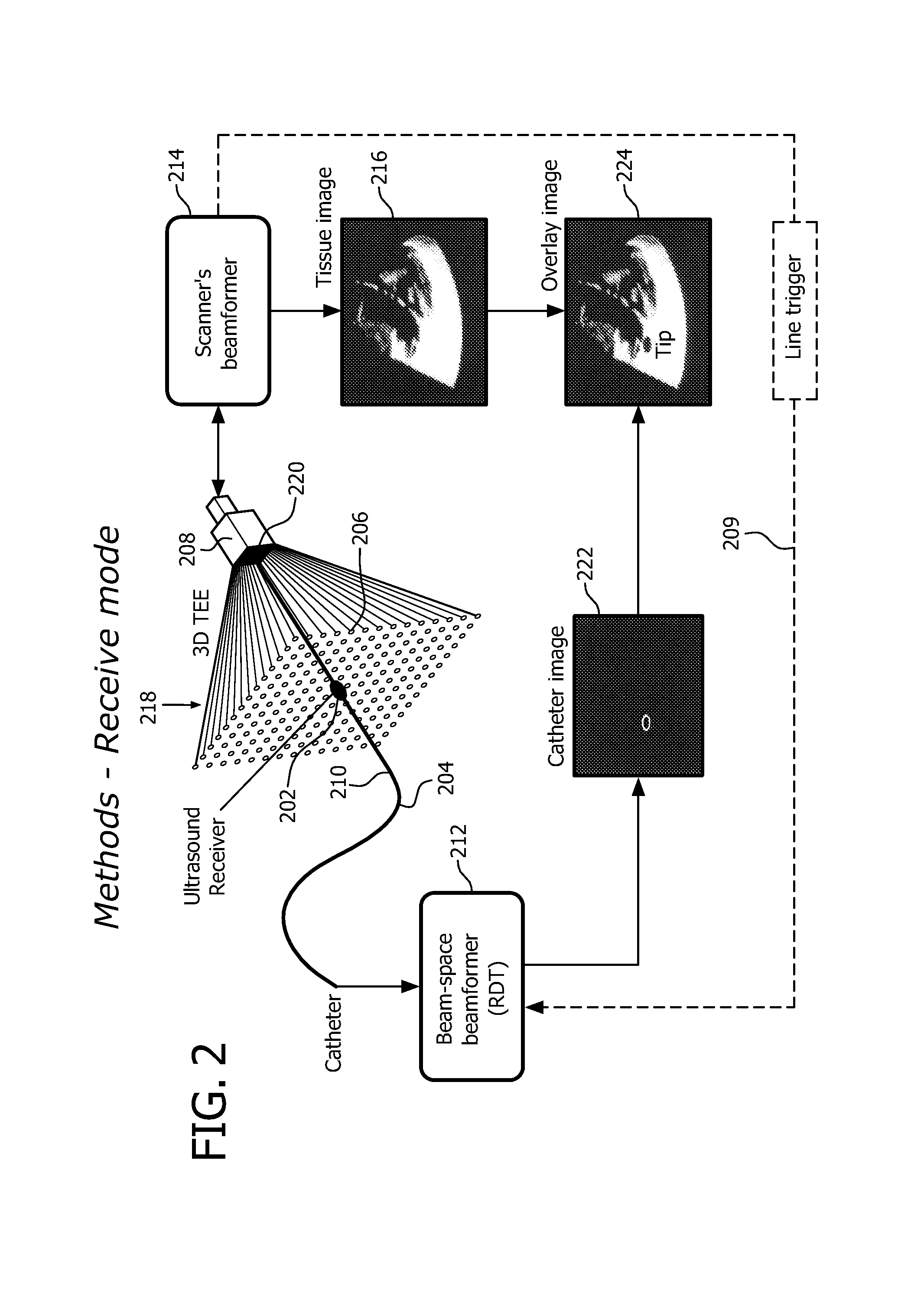
[0007]In the case of the ultrasound receiver, its 3D position can be obtained by beamforming the signals received by it as the ultrasound beams sweep the field of view during pulse-echo acquisition. In accordance with this technique, the ultrasound scanner scans using synthetic aperture with virtual transducers. The effect is to allow sensitive and specific catheter imaging, with perfect accuracy and the same resolution as that of the ultrasound imaging scanner at the same depth.
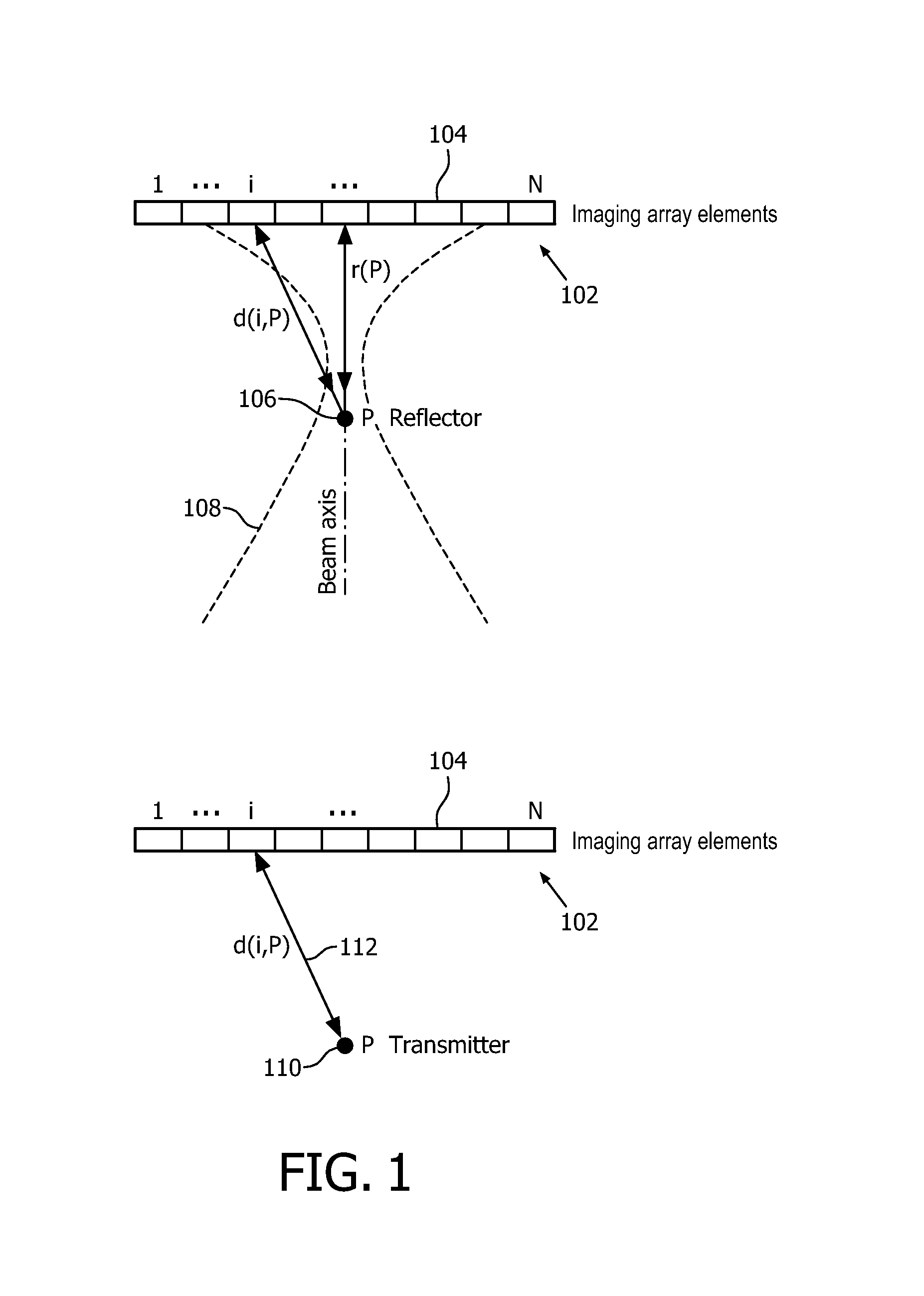
[0008]In other embodiments, in which to ultrasound transducer(s) can be either transmitters or receivers, tracking and pulse-echo image acquisition are separated by means of frequency or by means of timing (e.g., alternating, or otherwise interspersing, imaging frame with tracking frames). For example, such a transmitter, in the case of timing separation, may be triggered active in transmit by the line or frame trigger of an ultrasound scanner that temporarily interrupts its pulse-echo imaging of the medium of interest. Propagation of sound then occurs from the transmitter to the individual elements of the imaging array. The transmitter can be precisely imaged by adjusting the ultrasound scanner's beamforming delays to account for the one-way only propagation of transmissive ultrasound between the tracked ultrasound transmitter and the imaging array.

Problems solved by technology

However, many surgical tools are difficult to image with conventional pulse-echo ultrasound.
For instance, the usability of 3D Transoesophagial Echocardiography (3D-TEE) for guidance of catheter cardiac interventions is still limited because it is challenging to image catheters reliably with ultrasound.
Also, due to weak reflection, signal from the catheter may be drowned in signal from the surrounding anatomy.
However, the positioning accuracy of such sensors can get really poor (of the order of 10 mm) in EM distorted operating environment.
Additionally, an independent EM tracking system adds to the equipment cost and clutter in the catheter laboratory.
Furthermore, all embodiments described in that patent results in a very bad lateral resolution of the needle tip because there is no proper transmit focusing.

Method used


Image

  • Ultrasonic tracking of ultrasound transducer(s) aboard an interventional tool
  • Ultrasonic tracking of ultrasound transducer(s) aboard an interventional tool
  • Ultrasonic tracking of ultrasound transducer(s) aboard an interventional tool

Examples


Embodiment Construction

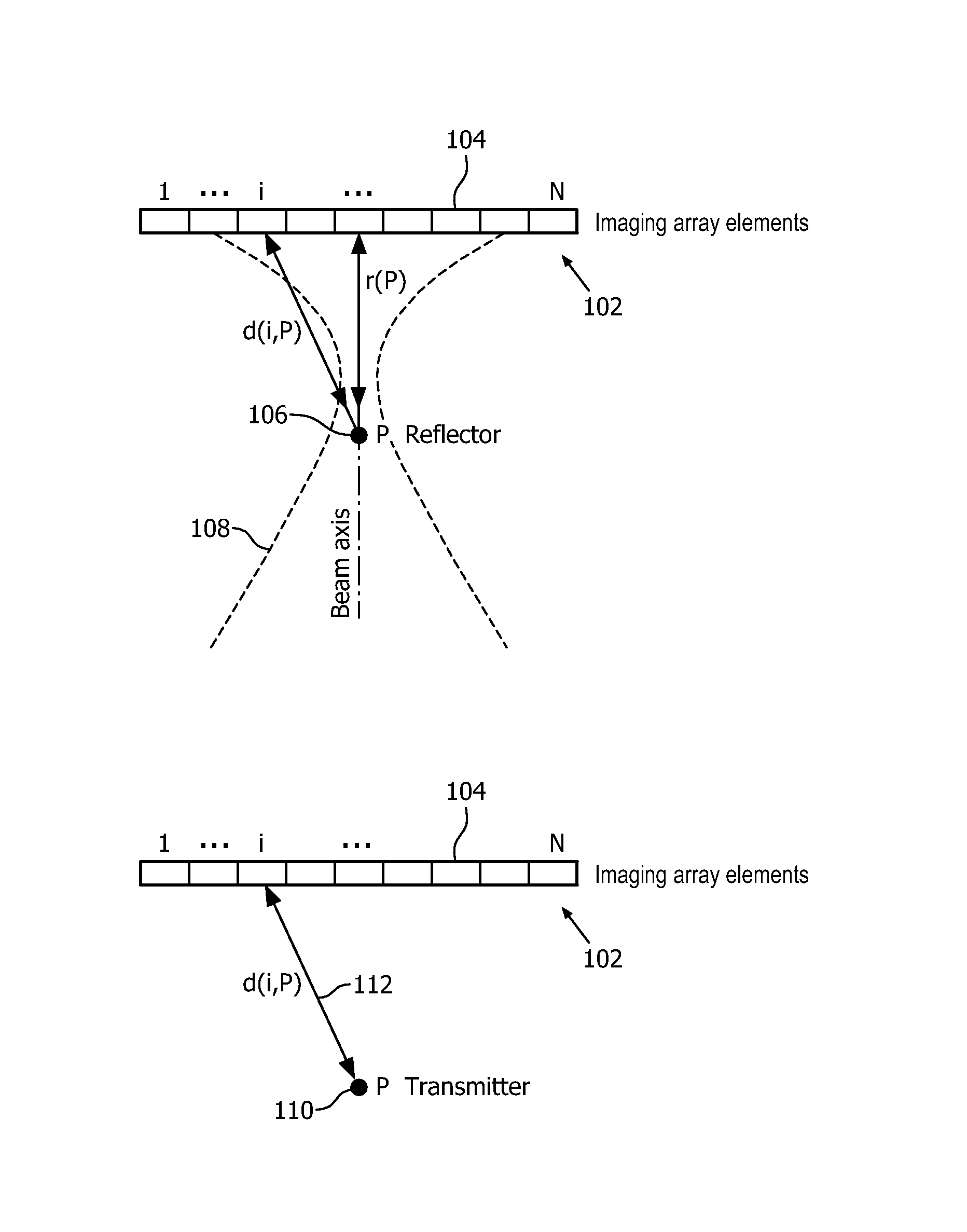
[0045]FIG. 1 offers, by way of illustrative and non-limitative example, a comparison between two-way beamforming and one-way only beamforming. The top figure, representative of two-way beamforming shows an imaging array 102 of N elements 104 issuing ultrasound that impinges on a reflector 106. Since the ultrasound waves go out and back (from the imaging array to the reflectors and back to the imaging array), we talk of “two-way” or “round-trip” beamforming. On receive (of the ultrasound that has reflected back), beamforming determines the reflectivity of the reflector 106 and the position of the reflector relative to the array 102. The array 102 send out a beam 108 that reflects off reflector 106 and returns to all elements 104 of the array 102. The flight of the pulse is over a distance r(P)+d(i,P) for element i. Each element 104 measures continually the amplitude of the return ultrasound. For each element 104, the time until a maximum of that measurement, i.e., the “round-trip tim...


PUM


Abstract

In one aspect, an ultrasound receive beamformer is configured for one-way only beamforming of transmissive ultrasound using one-way delays. The receive beamforming in some embodiments is used to track, in real time, a catheter, needle or other surgical tool within an image of a region of interest. The tool can have embedded at its tip a small ultrasound transmitter or receiver for transmitting or receiving the transmissive ultrasound. Optionally, additional transducers are fixed along the tool to provide the orientation of the tool.

Description

CROSS-REFERENCE TO RELATED APPLICATION[0001]This application is a national stage application under 35 U.S.C. §371 of International Application No. PCT / IB2011 / 051729 filed Apr. 20, 2011, which claims priority to U.S. Provisional Application Ser. No. 61 / 330,641 filed on May 3, 2010, which is incorporated herein by reference.FIELD OF THE INVENTION[0002]The present invention is directed to one-way only beamforming of transmissive ultrasound and, more particularly, to using such beamforming for tracking an interventional tool during real-time imaging.BACKGROUND OF THE INVENTION[0003]Precise visualization of catheters and real-time knowledge of their localization with respect to the anatomy are needed for minimally invasive interventions. Intra-operative ultrasound is often used for these purposes. However, many surgical tools are difficult to image with conventional pulse-echo ultrasound. For instance, the usability of 3D Transoesophagial Echocardiography (3D-TEE) for guidance of cathete...

Claims


Application Information

Patent Timeline
Patent Type & Authority Patents(United States)
IPC IPC(8): A61B8/00A61B8/12A61B8/08G01S7/52G01S15/89
CPCA61B8/12A61B8/0841A61B8/4488A61B8/483A61B34/20G01S7/52085G01S15/8915G01S15/8993G01S15/8997A61B2090/3782A61B8/5207
Inventor VIGNON, FRANCOIS GUY GERARD MARIESHI, WILLIAM TAOROBERT, JEAN-LUCJAIN, AMEET KUMARGUTIERREZ, LUIS FELIPE
Owner KONINK PHILIPS ELECTRONICS NV
Learn More