Apparatus and method for processing graphics primitives

a technology of primitives and apparatus, applied in the field of computer graphics, can solve the problems of significant impact on the area and power consumption of the circuitry, and achieve the effects of reducing the area and power consumption requirements, improving performance, and improving performan

Active Publication Date: 2016-03-15
ARM LTD
View PDF3 Cites 0 Cited by
  • Summary
  • Abstract
  • Description
  • Claims
  • Application Information

AI Technical Summary

Benefits of technology

[0017]In accordance with the present invention, the apparatus can determine dynamically which circuitry to use to perform depth bound clipping, dependent upon the presence or absence of a predetermined condition, in order to improve performance and reduce area requirements of the apparatus. In particular, in the default mode of operation depth bound clipping circuitry is used to perform a depth bound clipping operation by reviewing each graphics fragment, and in particular determining whether a depth value for that graphics fragment is within a valid depth range of a view frustum. If not, the graphics fragment is discarded from further processing. However, if the depth bound clipping circuitry was to be configured so as to be able to perform the depth bound clipping operation under all conditions, this would have a significant impact on the area and power consumption of that circuitry.
[0018]To alleviate the area and power consumption requirements, in accordance with the present invention, on detection of a predetermined condition, the depth bound clipping circuitry is disabled in order to disable performance of the depth bound clipping operation by that circuitry, and instead the operation of the primitive setup circuitry and the rasterization circuitry is modified in order to incorporate depth bound clipping within the rasterization operation. Whilst this has an impact on the performance of the rasterization operation, it is an area efficient mechanism for performing depth bound clipping.
[0019]Hence, by providing the two separate mechanisms for performing depth bound clipping, and switching between those mechanisms dependent on the presence or absence of a predetermined condition, the apparatus is able to maintain high performance whilst reducing the area and power consumption requirements of the apparatus.
[0020]There are a number of ways in which the control circuitry can be configured to modify the operation of the primitive setup circuitry and the rasterization circuitry. In one embodiment, the control circuitry is configured to modify the operation of the primitive setup circuitry by causing the primitive setup circuitry to additionally determine at least one depth plane edge function for the input graphics primitive. In addition, the control circuitry is configured to modify the operation of the rasterization circuitry by causing the rasterization circuitry to incorporate said at least one depth plane edge function in said rasterization operation. By such an approach, the rasterization operation can be arranged to exclude any region of the input graphics primitive which lies outside the valid depth range as identified by said at least one depth plane edge function, so that no graphics fragments will be generated for any such region. Since no graphics fragments will be generated for any such region, there is then no need for the depth bound clipping circuitry to perform the depth bound clipping operation, the depth bound clipping having effectively been incorporated within the modified rasterization operation.
[0024]The predetermined condition that causes the control circuitry to modify the operation of the primitive setup circuitry and the rasterization circuitry for one or more input graphics primitives can take a variety of forms, but in one embodiment is a condition indicating that a depth bias is enabled for said one or more input graphics primitives. If the depth bound clipping circuitry was to be configured so as to be able to perform the depth bound clipping operation under situations where depth bias is enabled, this would have a significant impact on the area and power consumption of the apparatus due to the need to pipe the extra depth bias information through multiple parts of the apparatus to the depth bound clipping circuitry, and to provide the additional circuitry required within the depth bound clipping circuitry. By instead disabling the depth bound clipping circuitry in such situations, and incorporating depth bound clipping within the rasterization operation, a significant improvement in the area and power consumption requirements of the apparatus can be achieved.
[0028]Additionally, in one embodiment, in said default mode of operation, the depth bound clipping circuitry is configured to selectively perform the depth bound clipping operation and said depth testing operation together, so that the depth value is only calculated once per graphics fragment and then used for both said depth bound clipping operation and said depth testing operation. This provides a particularly efficient implementation by avoiding the need to calculate the depth value twice, once for depth bound clipping and once for depth testing. In one embodiment, this approach is only performed selectively, since in certain cases side-effect issues will require that the depth clipping operation is performed before shader invocation, and depth testing is performed after shader invocation. Hence, in such cases the depth bound clipping and depth testing operations must be performed separately via two passes through the depth bound clipping circuitry. In situations where cases with such side-effects occur in the presence of the earlier mentioned predetermined condition (for example when depth bias is enabled), then this separation is achieved by performing depth bound clipping within the rasterization circuitry, avoiding the need to utilize the depth bound clipping circuitry twice (in this situation the depth bound clipping circuitry just performing depth testing).

Problems solved by technology

However, if the depth bound clipping circuitry was to be configured so as to be able to perform the depth bound clipping operation under all conditions, this would have a significant impact on the area and power consumption of that circuitry.

Method used


Image

  • Apparatus and method for processing graphics primitives
  • Apparatus and method for processing graphics primitives
  • Apparatus and method for processing graphics primitives

Examples


Embodiment Construction

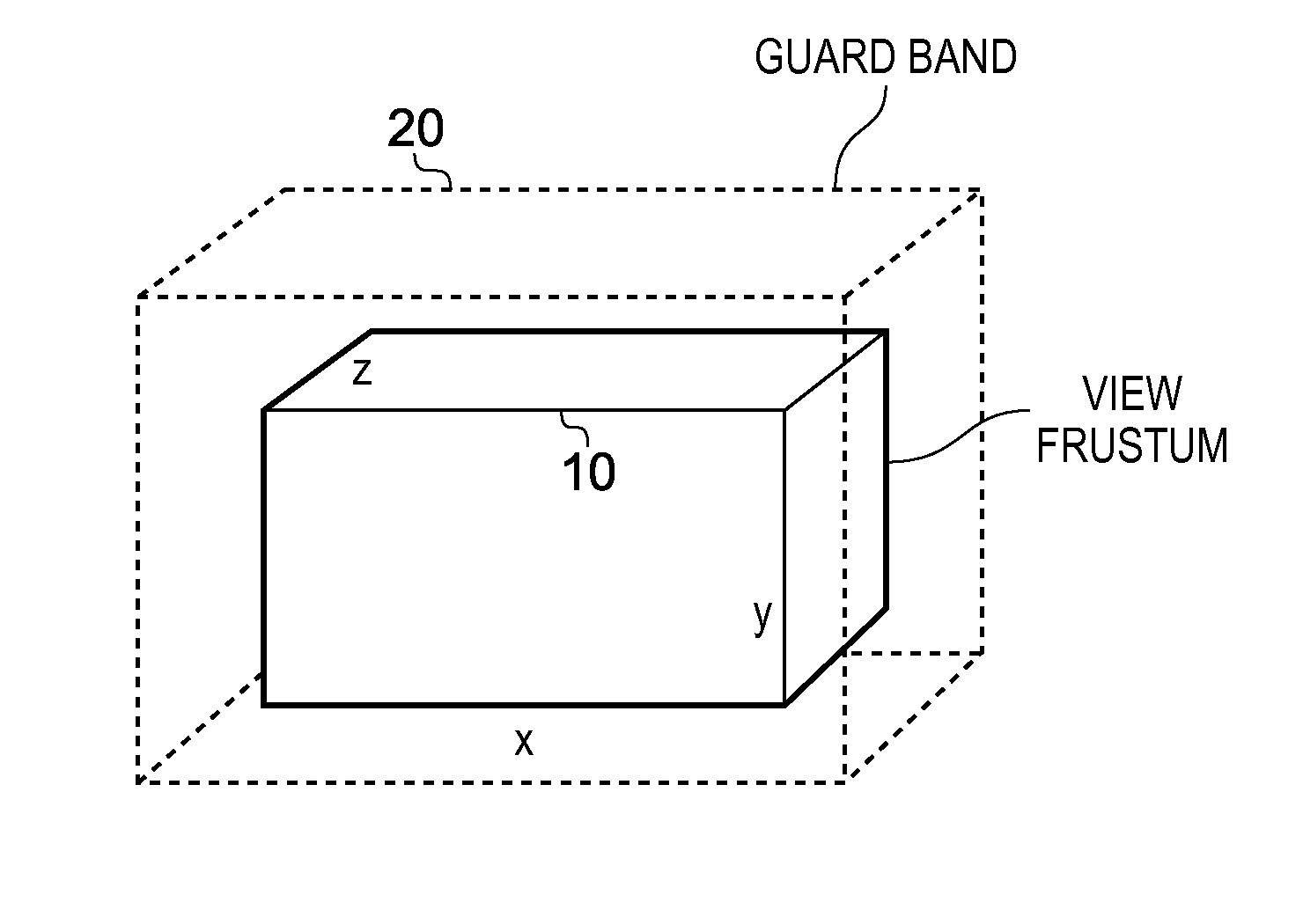
[0041]FIG. 1 schematically shows a guard band arrangement provided in association with a view frustum. The view frustum 10 represents the three-dimensional volume within which primitives may need to be rendered for display. The top, left, bottom and right edge planes define a viewport (which typically corresponds to the size of the display screen), whilst near and far depth planes represent the front and back planes of the view frustum (representing the closest and furthest distances at which objects can appear).

[0042]As shown in FIG. 1, a guard band 20 can be provided around the view frustum 10 in order to reduce the amount of clipping required during initial geometry processing prior to rasterization and rendering. However, primitives that extend beyond the edges of the guard band would still need to be clipped. In order to avoid the requirement for such clipping, it is known to set the clipping area edge planes of the guard band to infinity, to effectively define an infinite guar...


PUM


Abstract

A method and apparatus includes primitive setup circuitry for determining a plurality of functions for an input graphics primitive, including an edge function associated with each edge of the input graphics primitive and a depth function associated with the input graphics primitive. Rasterization circuitry performs a rasterization operation in order to calculate position data for a plurality of graphics fragments to be used to represent the input graphics primitive. In a default mode of operation, depth bound clipping circuitry performs a depth bound clipping operation by determining, for each graphics fragment in said plurality of graphics fragments, a depth value for said graphics fragment using the depth function, and determining whether said depth value resides within a valid depth range of a view frustum, the graphics fragment being discarded from further processing if its depth value does not reside within said valid depth range.

Description

BACKGROUND OF THE INVENTION[0001]1. Field of the Invention[0002]The present invention relates to the processing of computer graphics, and in particular to an apparatus and method for processing graphics primitives in order to generate a scene for display.[0003]2. Description of the Prior Art[0004]When processing 3D graphics, a scene to be displayed is typically split into a number of basic components called “primitives” in order to allow the 3D graphics processing operations to be more readily carried out. The primitives are usually in the form of simple polygons, such as triangles.[0005]Each primitive is typically defined by the vertices that make up the primitive, and each vertex will have associated with it particular data values representing the primitive at the vertex position, for example the X and Y position of the vertex, a depth (Z) value, colour and transparency values, etc. Within the graphics processing system, a primitive setup stage is performed that uses the data defi...

Claims


Application Information

Patent Timeline
Patent Type & Authority Patents(United States)
IPC IPC(8): G06T15/30G06T11/40G06T15/40
CPCG06T15/40G06T15/30G06T2200/28
Inventor HEGGELUND, FRODEOSTBY, KENNETH EDVARD
Owner ARM LTD
Why Eureka
Try Eureka