Photovoltaic system power tracking method

a photovoltaic system and power tracking technology, applied in the field of photovoltaic systems, can solve the problems of general non-uniform radiation pattern projected onto the receiver, loss of light intensity, general non-uniformity, etc., and achieve the effects of increasing the electrical power generated by the photovoltaic cell, maximizing solar power, and increasing the reliability of the system

Active Publication Date: 2016-03-22
SOLAREDGE TECH LTD
View PDF1281 Cites 93 Cited by
  • Summary
  • Abstract
  • Description
  • Claims
  • Application Information

AI Technical Summary

Benefits of technology

[0009]According to the present invention there is provided a method for controlling a photovoltaic system including a photovoltaic cell and an electronic module connected to the photovoltaic cell. One or more control signals are produced indicative of electrical power being generated by the photovoltaic cell. The control signal(s) are received and based on the control signals, a tracking motor for adjusting the system is adjusted. Electrical power generated by the photovoltaic cell is thus increased and preferably maximized. Maximum power point power tracking may also be performed by maximizing electrical power individually from said photovoltaic cells at either respective the inputs or outputs of the electronic modules. The maximum power point tracking may be performed independently from the control of the tracking motor for adjusting the system by performing the maximum power point tracking and the opto-mechanical adjustments in either different time domains or different frequency domains. In one embodiment, the MPPT control over the output voltage and current of the cells, and the tracker control, could be done by one integrated control unit. The adjustments preferably include orienting an optical component of the system in at least one of two angles toward the Sun. The opto-mechanical adjustments may include varying a distance of at least one optical component within the system such as a focus distance or a distance of an optical diffuser in the system. The control of the opto-mechanical adjustment may be performed based on a prior selection of one or more of the photovoltaic cells / signals. When there are multiple photovoltaic cells and electronic modules connected thereto, different photovoltaic cells with different control signals may be reselected periodically to maximize solar power on the different photovoltaic cell to increase reliability of the system. Alternatively, the control system may maximize the aggregate output power of all PV cells rather than focusing on some of them.

Problems solved by technology

The resulting irradiance pattern projected onto the receiver is generally non-uniform.
Although the secondary reflector can improve the uniformity of the pattern of light on the receiver cells, some non-uniformity generally persists and the additional reflections in the secondary generally result in some loss of light intensity.
Additional loss of incident light may result from tracking errors that occur while the concentrator attempts to locate the sun or re-locate the sun after it reemerges from behind cloud cover, for example.

Method used


Image

  • Photovoltaic system power tracking method
  • Photovoltaic system power tracking method
  • Photovoltaic system power tracking method

Examples


Embodiment Construction

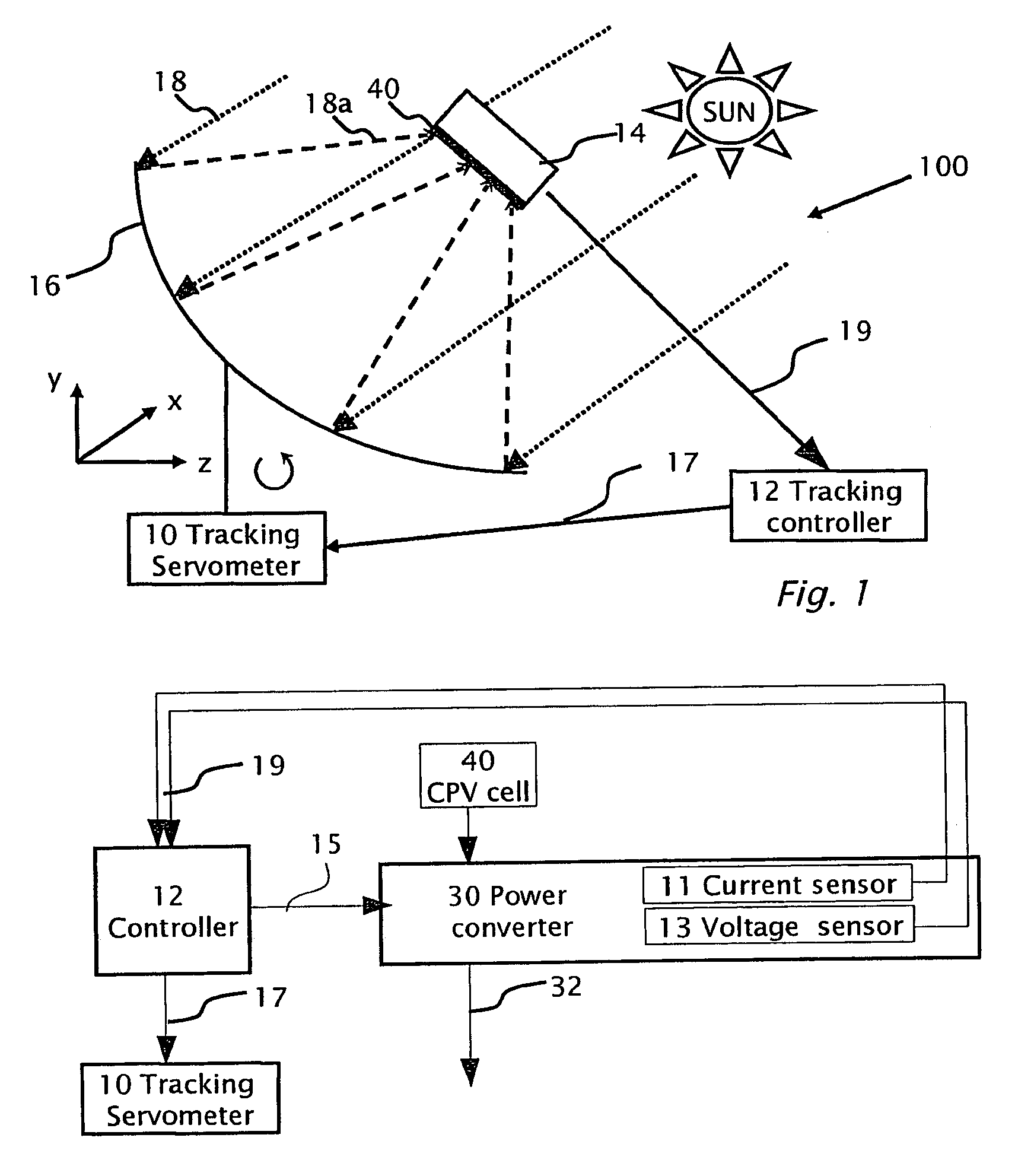
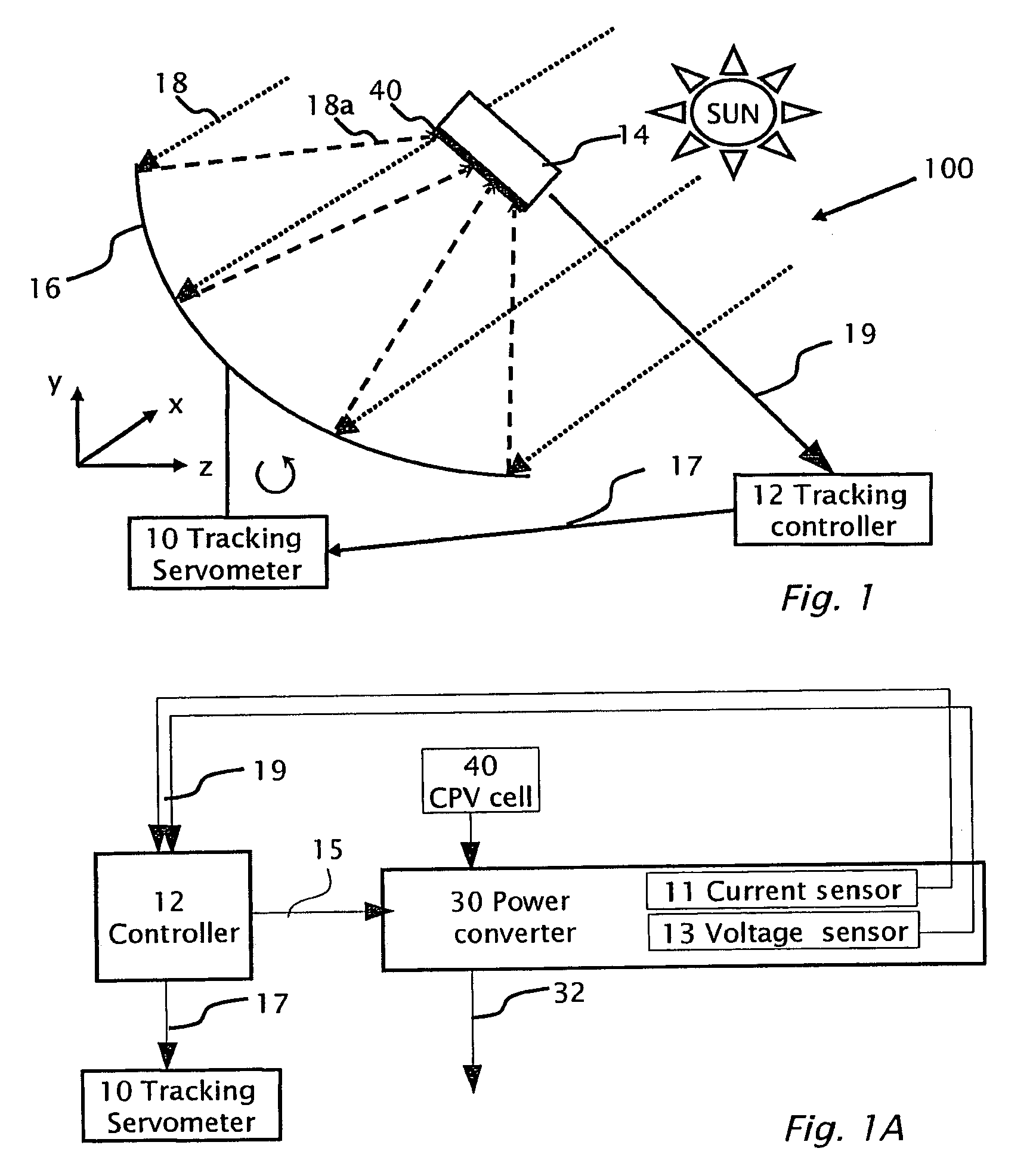
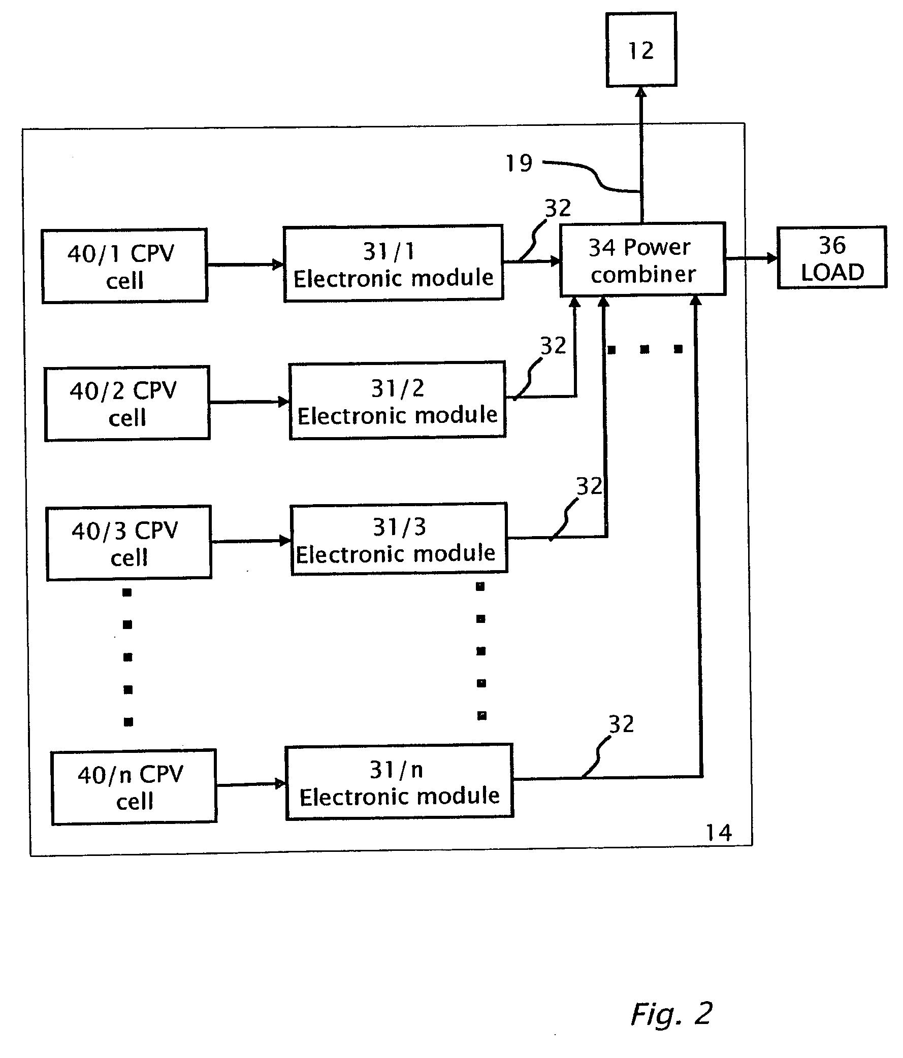
[0018]Reference will now be made in detail to embodiments of the present invention, examples of which are illustrated in the accompanying drawings, wherein like reference numerals refer to the like elements throughout. The embodiments are described below to explain the present invention by referring to the figures.

[0019]Implementation of the method and system of embodiments of the present invention involves performing or completing selected tasks or steps manually, automatically, or a combination thereof. Moreover, according to actual instrumentation and equipment of preferred embodiments of the method and system of the present invention, several selected steps could be implemented by hardware or by software on any operating system of any firmware or a combination thereof. For example, as hardware, selected steps of the invention could be implemented as discrete integrated circuit, a system on chip an ASIC, or other circuit. Similar, control functions as described herein may be perf...


PUM


Abstract

A photovoltaic system including a photovoltaic cell, and an electronic module connected to the photovoltaic cell. The electronic module is adapted to produce at least one control signal indicative of electrical power being generated by the photovoltaic cells. A tracking controller is adapted to receive the control signal(s) and based on the control signal(s), the controller is adapted to control a tracking motor for adjusting the system so that electrical power generated by the photovoltaic cells is increased. The photovoltaic system may include an optical element, adapted for concentrating solar light onto the photovoltaic cells. The electronic module preferably performs direct current (DC) to direct current (DC) power conversion and maximum power point tracking by electrical power, current, or voltage at either their inputs or their outputs. Alternatively, the tracking controller is configured to also perform maximum power point tracking by increasing to a local maximum electrical power by varying at least one of (i) current or voltage output from the photovoltaic cell or (ii) current or voltage output from the electronic module.

Description

CROSS REFERENCE TO RELATED APPLICATIONS[0001]The present application benefits from U.S. 60 / 992,589 filed by the present inventors filed on Dec. 5, 2007.TECHNICAL FIELD[0002]The present invention relates to photovoltaic systems and more specifically to solar tracking and other opto-mechanical adjustments particularly applicable for optimizing performance of concentrated photovoltaic systems.DESCRIPTION OF RELATED ART[0003]In a concentrated photovoltaic (CPV) system, high-efficiency cells are typically used, on which concentrated sunlight is directed in order to increase the power production of the system. Therefore, in CPV systems it is important to track the sun so as to maintaining the concentrating sunlight focused on the solar cells. Solar concentrators employ reflectors, lenses, or a combination thereof to concentrate incident light on one or more photovoltaic cells or light receiver. The resulting irradiance pattern projected onto the receiver is generally non-uniform. The inte...

Claims


Application Information

Patent Timeline
Patent Type & Authority Patents(United States)
IPC IPC(8): G01S3/786H02J3/46H02M7/493H01L31/00H02J13/00H02J3/38H02M7/44H02M1/00H01L31/042F24S50/20
CPCG01S3/7861H02J3/385H02J3/46H02J13/0003H02M7/44H02M7/493H02J2003/388H02M2001/0077Y02E10/52Y02E10/58Y10T307/685H02J2300/26H02J3/381Y02E10/56H02M1/0077H02J3/388
Inventor ADEST, MEIRSELLA, GUYHANDELSMAN, LIORGALIN, YOAVFISHELOV, AMIR
Owner SOLAREDGE TECH LTD
Why Eureka
Try Eureka