Electric machine with Q-offset grooved interior-magnet rotor and vehicle

a technology of magnetic rotor and electric machine, which is applied in the direction of hybrid vehicles, magnetic circuit rotating parts, and shape/form/construction of magnetic circuits, etc., can solve the problems of noise and vibration, low speed ride comfort, and torque fluctuations of motors, so as to improve efficiency, reliability, cost performance or productivity. the effect of motor performan

Active Publication Date: 2016-03-29
HITACHI ASTEMO LTD
View PDF87 Cites 10 Cited by
  • Summary
  • Abstract
  • Description
  • Claims
  • Application Information

AI Technical Summary

Benefits of technology

[0026]According to the present invention, the performance (for example, efficiency, reliability, cost performance, or productivity) of a motor can be improved.

Problems solved by technology

Torque fluctuations of a motor are causes of noises and vibrations.
In particular, in the case of electric vehicles, there arises the problem that the torque fluctuations make the ride uncomfortable at low speeds.

Method used


Image

  • Electric machine with Q-offset grooved interior-magnet rotor and vehicle
  • Electric machine with Q-offset grooved interior-magnet rotor and vehicle
  • Electric machine with Q-offset grooved interior-magnet rotor and vehicle

Examples


first embodiment

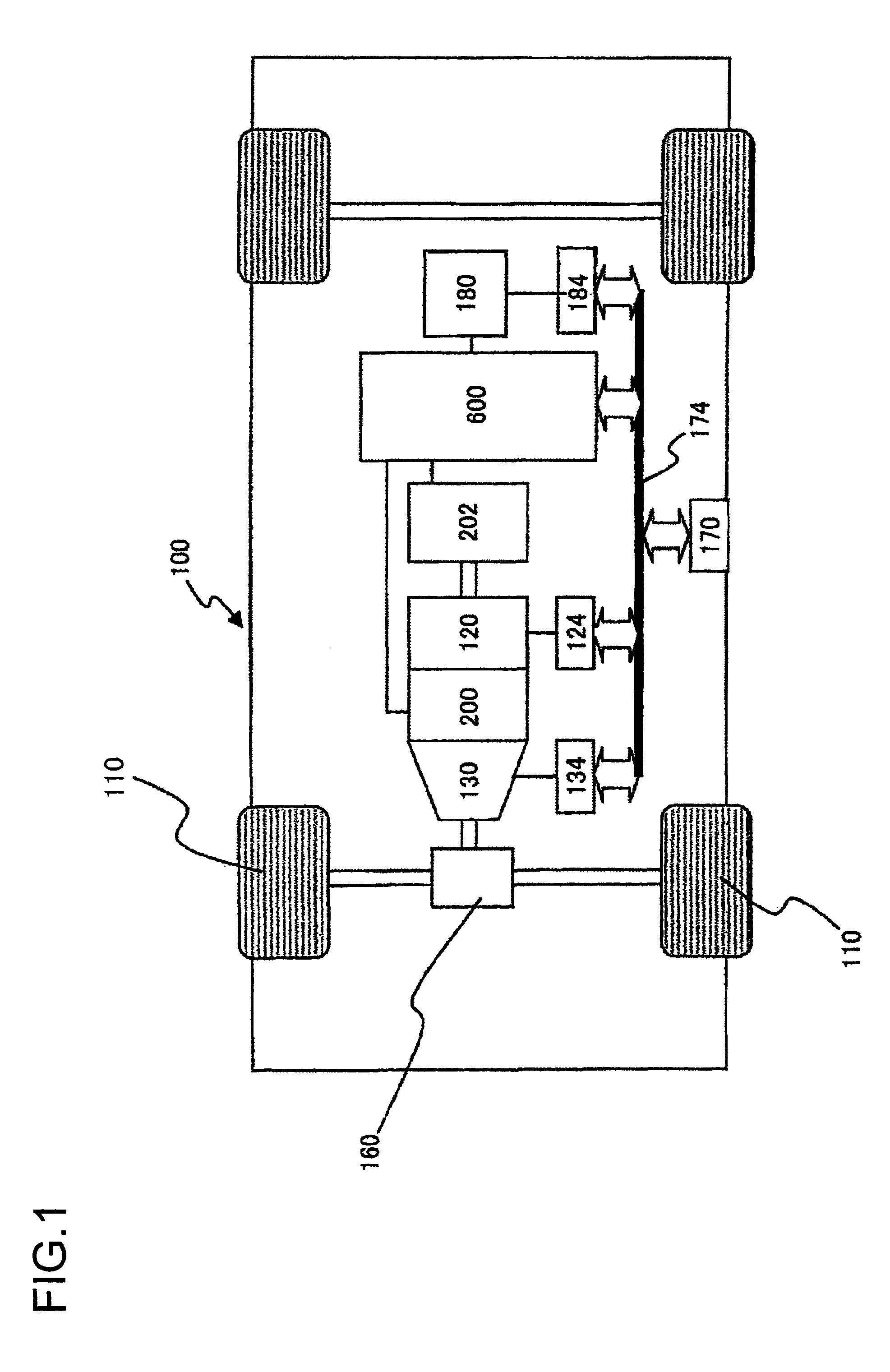
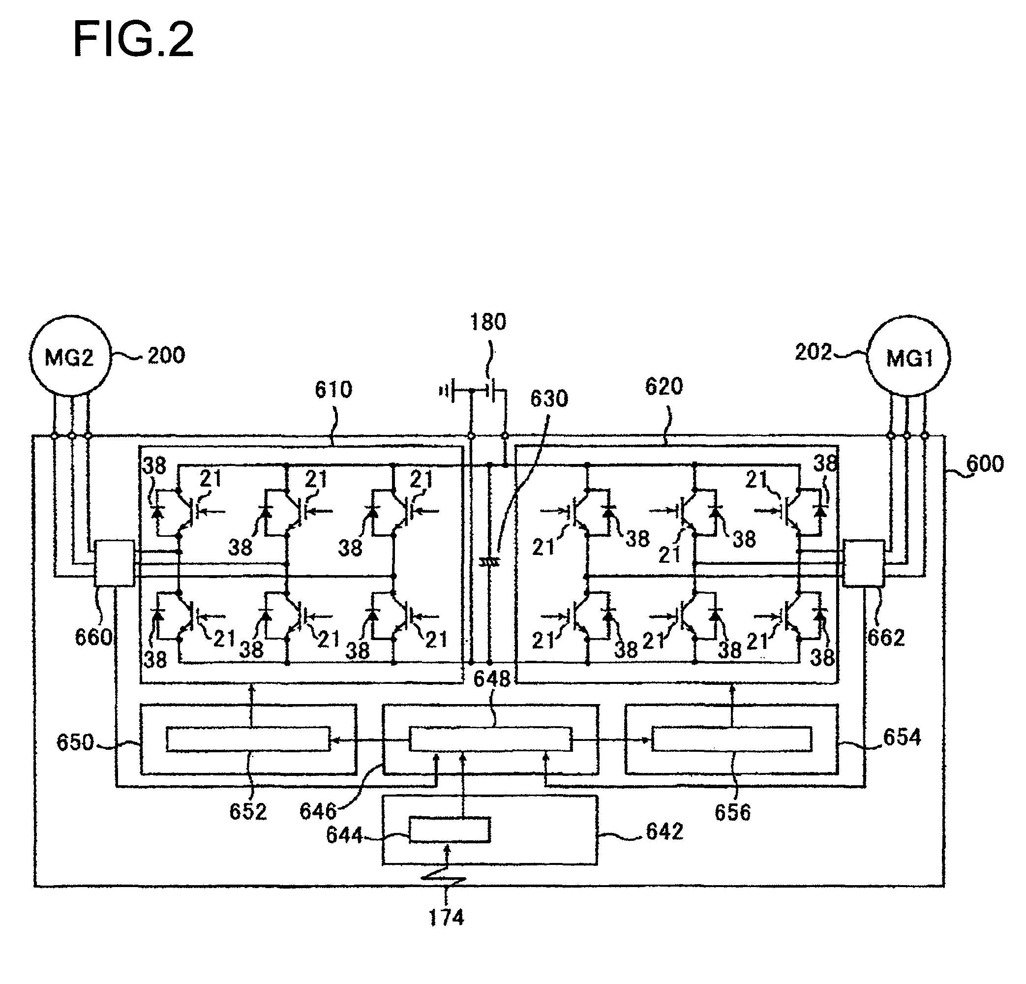
[0072]FIG. 1 presents a schematic diagram showing the construction of a hybrid electric vehicle having mounted thereon a rotating electric machine according to an embodiment of the present invention. A vehicle 100 has mounted thereon an engine 120 and a first rotating electric machine 200, a second rotating electric machine 202, and a battery 180. The battery 180 supplies direct current power to the rotating electric machines 200 and 202 when driving forces of the rotating electric machines 200 and 202 are required and the battery 180 receives direct current power from the rotating electric machines 200 and 202 upon regenerative driving. Transfer of direct current power between the battery 180 and the rotating electric machines 200 and 202 is conducted through a power converter unit 600. Though not shown, the vehicle has mounted thereon a battery that supplies low voltage power (for example, 14-volt power) and supplies direct current power to a control circuit, which is explained he...

second embodiment

[0125]FIGS. 15(a) and 15(b) show a rotor according to another embodiment of the present invention. The present embodiment is the same as the first embodiment excepting what is explained hereafter.

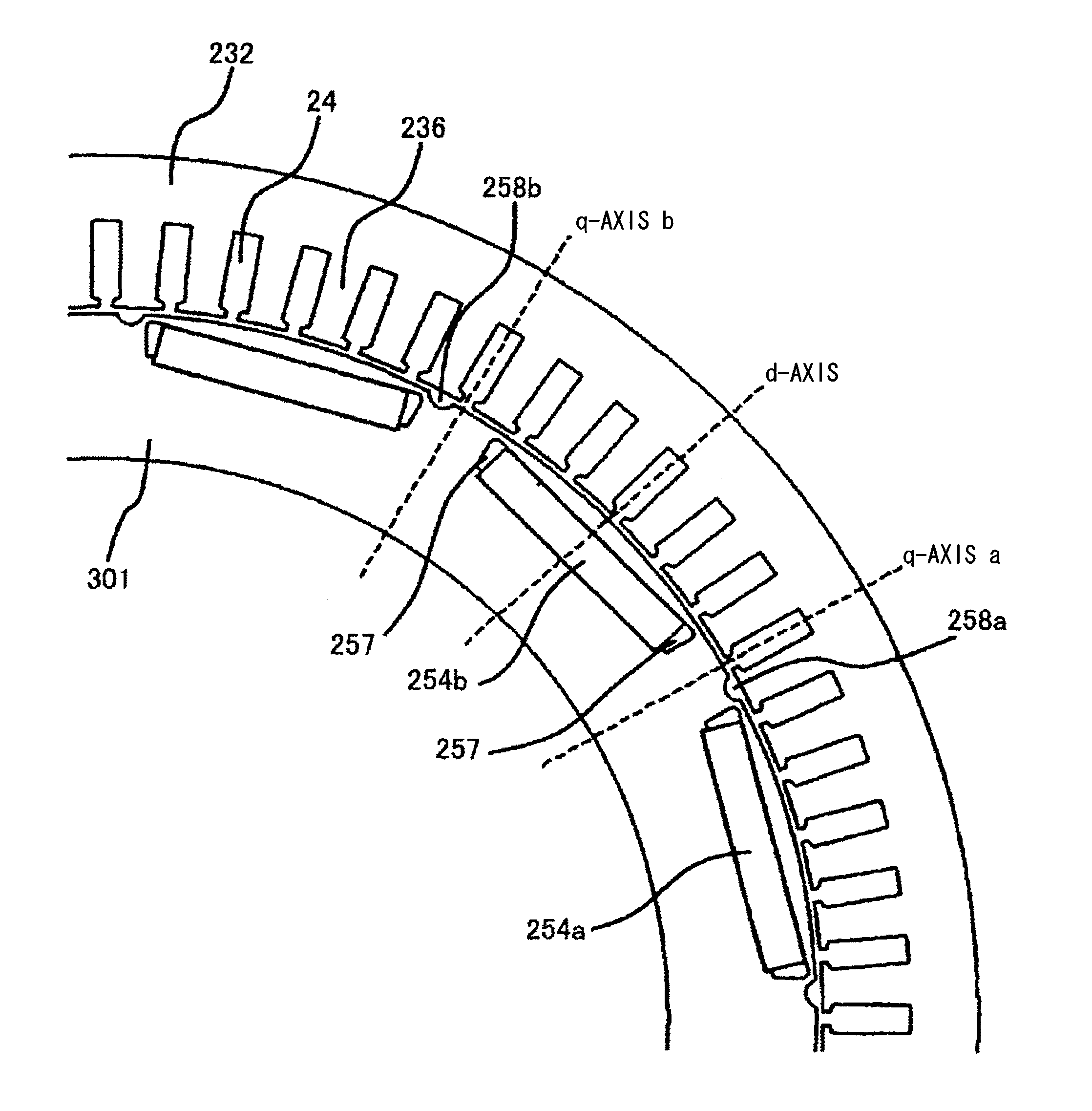
[0126]FIG. 15(a) shows a rotor of the surface magnet type and FIG. 15(b) shows a rotor in which a plurality of magnets is arranged in a V-shape. In either type of the rotor, the assisted salient pole member 259 is between any two adjacent permanent magnets 254 and the magnetic air gap 258 is arranged in the assisted salient pole member 259. Assuming that as seen from the inner periphery of the rotor 250, a central axis between the permanent magnet 254a and a next magnet on the left side of the permanent magnet 254a is named q-axis a and a central axis between the permanent magnet 254b and a next magnet on the left side of the permanent magnet 254b is named q-axis b, the magnetic air gap 258a is arranged offset to the right with respect to the q-axis a and the magnetic air gap 258b is arrang...

third embodiment

[0127]FIG. 16 illustrates achievement of reduction of torque fluctuations by providing two magnetic air gaps 258 for each assisted salient pole member 259 according to the present embodiment.

[0128]This shape is as follows. Assuming that as seen from the inner periphery of the rotor 250, a central axis between the permanent magnet 254a and a next magnet on the left side of the permanent magnet 254a is named q-axis a and a central axis between the permanent magnet 254b and a next magnet on the left side of the permanent magnet 254b is named q-axis b, the magnetic air gap 258a on the right side with respect to the q-axis a is larger and the magnetic air gap 258e on the left side with respect to the q-axis b is smaller. The magnetic air gap 258b on the right side with respect to the q-axis b is larger and the magnetic air gap 258f on the left side with respect to the q-axis b is smaller. The magnetic air gaps 258a and 258b and the magnetic air gaps 258e and 258f are arranged symmetric w...


PUM


Abstract

A rotating electric machine includes a stator having a stator coil and a rotor provided rotatably around a specific rotation axis with respect to the stator. The rotor includes a plurality of magnets, a plurality of magnetically-assisted salient pole members provided between poles of any adjacent two magnets from among the plurality of magnets, and a magnetoresistance variation unit provided in the magnetically-assisted salient pole member along an axial direction of the rotation axis at a position offset in a circumferential direction of the rotation axis from a q-axis passing through a salient pole center of the magnetically-assisted salient pole member. The amount of offset of the magnetoresistance variation unit from the q-axis varies depending on positions of the magnetically-assisted salient pole members so that torque fluctuations cancel each other when power is applied.

Description

TECHNICAL FIELD[0001]The present invention relates to a rotating electric machine and an electric vehicle equipped with the rotating electric machine.BACKGROUND ART[0002]Motors for driving used in electric vehicles and hybrid vehicles are required to provide significant power output so that permanent magnet motors including a rare earth element that retains intense energy are generally used. The motors for driving use, from among such permanent magnet motors, embedded-type magnet motors, which can satisfy the requirement to provide a large torque at low speeds and a wide rotation speed range.[0003]Torque fluctuations of a motor are causes of noises and vibrations. In particular, in the case of electric vehicles, there arises the problem that the torque fluctuations make the ride uncomfortable at low speeds. Conventional motors generally adopt a countermeasure to provide skew in order to reduce the torque fluctuations. For example, there is known a motor in which an electromagnetic s...

Claims


Application Information

Patent Timeline
Patent Type & Authority Patents(United States)
IPC IPC(8): H02K1/27B60L15/02H02P27/06B60L11/14H02K7/00B60L11/12B60L15/20B60K1/02B60K6/26B60K6/445H02K29/03B60L15/00B60L50/15B60L50/16
CPCB60L15/025B60L15/20H02K1/276H02K7/006H02P27/06H02K1/2766B60L11/123B60L11/14B60K1/02B60K6/26B60K6/445B60L15/007B60L2210/10B60L2210/40B60L2220/14B60L2240/421B60L2240/423B60L2240/429B60L2240/443B60L2240/547B60L2240/549B60L2270/142B60L2270/145H02K29/03H02K2201/06Y02T10/6217Y02T10/6239Y02T10/641Y02T10/643Y02T10/7077Y02T10/7216Y02T10/7241Y02T10/7275B60L50/61B60L50/16Y02T10/64Y02T10/62Y02T10/72Y02T10/7072Y02T10/70H02K2213/03H02K1/22H02P21/00B60W10/08H02K1/24
Inventor SAITO, YASUYUKIGOTO, TSUYOSHINAKAYAMA, KENICHIHINO, NORIAKISUGIMOTO, SHINJI
Owner HITACHI ASTEMO LTD
Why Eureka
Try Eureka