Method of taking power with low-voltage bypass by integrated circuit for AC direct driving LEDs and the integrated circuit

a technology of integrated circuits and leds, applied in the field of electronics, can solve the problems of poor anti-surge performance, large useless power dissipated on the voltage-dropping power resistors, capacitor voltage drop technology, etc., and achieve the effects of low voltage, high efficiency, and reduced area of led chips and ic chips

Active Publication Date: 2016-03-29
HEFEI SPRUCE OPTOELECTRONICS TECH
View PDF13 Cites 12 Cited by
  • Summary
  • Abstract
  • Description
  • Claims
  • Application Information

AI Technical Summary

Benefits of technology

[0014]The present invention provides a method of taking power with low-voltage bypass by an IC for AC direct driving LEDs and the IC for AC direct driving LEDs that is suitable for applying the method of taking power with low-voltage bypass. The method of taking power with low-voltage bypass has the characteristics of simplicity in power-taking, low voltage and high efficiency, thus the areas of the board for LED chips and IC chips may be significantly reduced, and the reliability may be greatly improved. The IC of the present invention not only meets the requirements of low-voltage bypass power-taking technologies, but also has the advantages of low power consumption, high efficiency, high reliability, low cost, less pins, less external components and convenient use, etc.

Problems solved by technology

The existing resistor voltage drop technology has an apparent disadvantage that the useless power dissipated on the voltage-dropping power resistor is large.
The capacitor voltage drop technology has disadvantages of poor anti-surge performance, and low reliability.
The transformer technology has disadvantages of low efficiency and large volume.
The switching power supply technology has disadvantages of complex circuits and high cost.
Moreover, such an AC high voltage power taking technology has an especially critical technical disadvantage that, in the practical application, a large number of long AC high-voltage circuit wires will cause difficulty in the wiring between LEDs and ICs on printed circuit board (PCB), an increase in the area of the PCB and lower reliability.
Especially, for the chip on board (COB) technology that has been widely used and is continuously developing rapidly, namely, the technology of bonding LED chips and IC chips for AC direct driving LEDs on a ceramic or aluminum board, the existing AC high voltage power supplying technology for the IC for AC high voltage direct driving LEDs usually requires a large number of long and high-voltage connecting wires and electronic components with a high voltage of hundreds of volts, which significantly increases the area of the board for LED chips and IC chips, lowers the reliability of the products and increases the manufacturing cost.

Method used


Image

  • Method of taking power with low-voltage bypass by integrated circuit for AC direct driving LEDs and the integrated circuit
  • Method of taking power with low-voltage bypass by integrated circuit for AC direct driving LEDs and the integrated circuit
  • Method of taking power with low-voltage bypass by integrated circuit for AC direct driving LEDs and the integrated circuit

Examples


embodiment 1

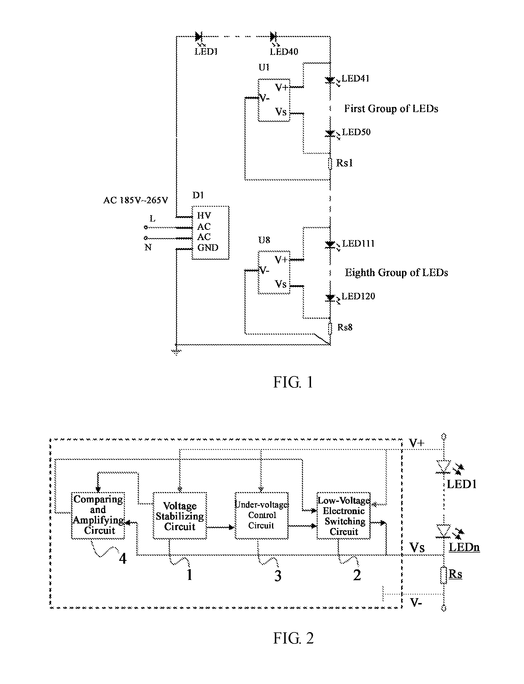
[0020]FIG. 1 shows a circuit diagram illustrating an application of an IC in accordance with the present invention along with a method of taking power with low-voltage bypass by the IC. The circuit diagram as shown by this figure includes: a bridge rectifier D1; eight ICs (from a first IC U1 to an eighth IC U8) in accordance with the present invention; a LEDs-load unit comprising forward biased LED1 to LED40 connected in series which are not controlled by the IC in accordance with the present invention and are always switched in; a LEDs-load unit comprising forward biased LED41 to LED50 connected in series which are controlled by the IC in accordance with the present invention; a first current sampling resistor Rs1 as an external current sampling resistor of the first IC U1; and, by analogy, tO an eighth controlled LEDs-load unit comprising an eighth group of forward biased LED111 to LED120 connected in series, along with an eighth current sampling resistor Rs8 as an external curren...

embodiment 2

[0024]FIG. 2 shows a block diagram illustrating a circuit configuration of the IC in accordance with the present invention. The IC comprises a voltage stabilizing circuit 1, a low-voltage electronic switching circuit 2, an under-voltage control circuit 3 and a comparing and amplifying circuit 4. The IC has three pins, i.e., a positive power-supply terminal V+, a common terminal Vs for current sampling and low-voltage electronic switching, and a zero potential reference terminal V−. The LED1 to LEDN connected in series in the same direction represent external loads, forming an external LEDs-load unit. Rs represents an external current sampling resistor of the IC. The voltage stabilizing circuit 1 has an input voltage corresponding to V+ for the IC, and has an output voltage of about 2.4V, which supplies power to the comparing and amplifying circuit 4. The voltage stabilizing circuit provides a low level output under an under-voltage input, and is connected to the input end of the und...

embodiment 3

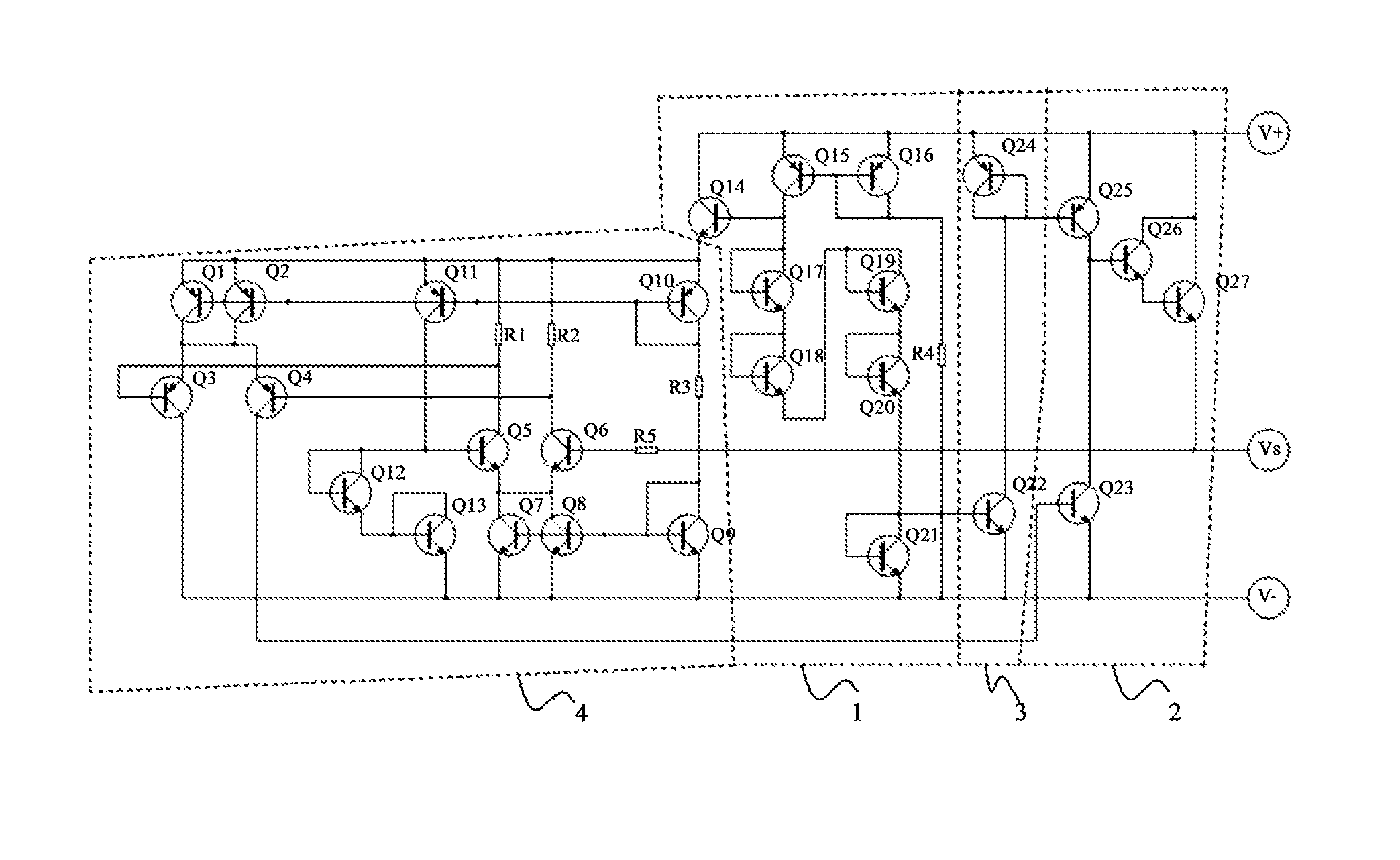
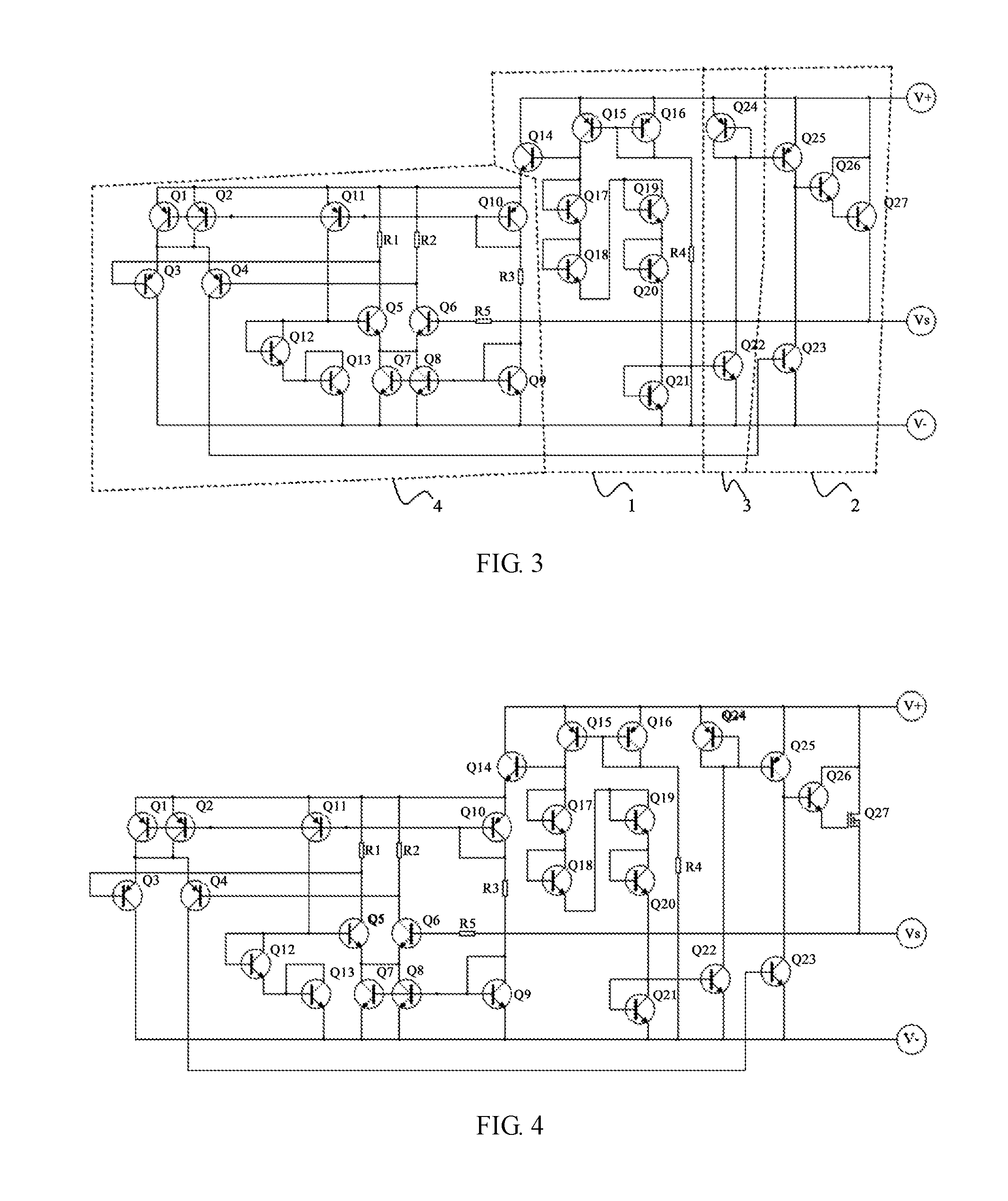
[0025]FIG. 3 shows an internal circuit diagram of the IC in accordance with the present invention applying a bipolar IC technology, which is an internal circuit diagram of an IC that is compatible with a bipolar IC technology. As shown in FIG. 3, the IC is an IC for AC direct driving LEDs suitable for taking power with low-voltage bypass, comprising a voltage stabilizing circuit 1, a low-voltage electronic switching circuit 2, an under-voltage control circuit 3 and a comparing and amplifying circuit 4, and provided with three pins, i.e., a positive power-supplied terminal, a common terminal for current sampling and low-voltage electronic switching, and a zero potential reference terminal. The positive power-supply terminal is connected to each of the voltage stabilizing circuit 1, the low-voltage electronic switching circuit 2 and the under-voltage control circuit 3; an output of the voltage stabilizing circuit 1 is connected to an input end of the under-voltage control circuit 3, t...


PUM


Abstract

Disclosed is a method of taking electric power from a low voltage bypass for providing low voltage power supply for an integrated circuit. Also provided is an alternating current (AC) directly driven LED integrated circuit adapted to use the method; the integrated circuit includes a voltage stabilizing circuit, a low voltage electronic switch circuit, an under-voltage control circuit, and a comparative amplification circuit, and has three pins, a positive power supply terminal, a zero potential reference terminal, and a common terminal for current sampling and for the low voltage electronic switch. The method of taking electric power from a low voltage bypass for providing low voltage power supply for an AC directly driven LED integrated circuit, and the integrated circuit adapted to use the method have the advantages of low power consumption and cost, high efficiency and reliability, and fewer pins and external devices, and are easy to use.

Description

CROSS-REFERENCE TO RELATED APPLICATIONS[0001]This application is a U.S. national stage application under 35 U.S.C. §371 of International Application No. PCT / CN2014 / 072539, filed Feb. 26, 2014, which in turn claims the benefit of Chinese Application No. 201310147248.6, filed Apr. 25, 2013, the content of each of which is incorporated herein by reference in its entirety.FIELD OF THE INVENTION[0002]The present invention relates to electronics, and in particular, relates to a method of taking power with low-voltage bypass by an integrated circuit (IC) for alternating current (AC) direct driving LEDs and the IC.BACKGROUND OF THE INVENTION[0003]The technologies of AC direct driving light emitting diodes (LEDs) have attracted a wide attention for their characteristics of simple structure, low cost, long lifetime and the like, and IC for AC direct driving LEDs is the key technology. However, in the existing technologies of IC for AC direct driving LEDs, all methods of supplying power for th...

Claims


Application Information

Patent Timeline
Patent Type & Authority Patents(United States)
IPC IPC(8): H05B33/08H05B44/00
CPCH05B33/0818H05B33/083H05B33/0827H05B45/48H05B45/3725H05B45/46
Inventor ZHAO, TIANPENG
Owner HEFEI SPRUCE OPTOELECTRONICS TECH
Why Eureka
Try Eureka