Electrochemical deposition apparatus with remote catholyte fluid management

a technology of catholyte fluid management and electrochemical deposition equipment, which is applied in the direction of electrolysis process, electrolysis components, semiconductor devices, etc., can solve the problems of inconvenient operation, large amount of equipment, and inconvenient maintenance, so as to facilitate the management of metal concentration and eliminate the cost and complexity.

Active Publication Date: 2016-04-05
ASMPT NEXX INC
View PDF149 Cites 3 Cited by
  • Summary
  • Abstract
  • Description
  • Claims
  • Application Information

AI Technical Summary

Benefits of technology

[0004]Conventional electro-chemical deposition tools include a processing tank containing a process electrolyte (catholyte). Substrates or wafers can then be lowered into the tank. In some configurations, an anode is positioned on a sidewall of the processing tank. Such a configuration is typically limiting because only one substrate in the processing tank can be plated. To increase yield, conventional electro-chemical deposition tools use multiple plating cells positioned within a tank of catholyte fluid, with each plating cell including an anode and a sealed anolyte fluid chamber combination, as well as openings in the plating cell for catholyte to circulate through the cell and across a substrate to be plated. Typically, catholyte is flowed from openings at a bottom of the plating cell across a vertically held wafer. The flow of catholyte fluid then spills over a linear weir, at the top of the plating cell, back into the processing tank of catholyte fluid to be reflowed across the substrate.
[0006]Techniques disclosed herein include an electro-chemical deposition apparatus that provides a simplified circulation system, better chemical management for more reliable and uniform plating, as well as short maintenance times for greater tool availability. Techniques include a processing tank containing an anolyte fluid, and one or more plating cells each having a catholyte fluid compartment having a circulation path that connects to a separate or remote catholyte reservoir. The anolyte fluid is not the process electrolyte and needs substantially less maintenance as compared to the catholyte fluid that needs constant replenishment of metal ions and other additives. Thus, with such a configuration as disclosed herein, a single pump can be used to flow catholyte (via manifolds) through one or more plating cells. The anolyte fluid in the processing tank can circulate inherently via fluid diffusion, or there can be an optional flow mechanism in the processing tank. Thus, with the catholyte reservoir maintained off board, instead of dumping catholyte over a weir into a reservoir, catholyte fluid—after flowing through a plating cell—is returned to the catholyte reservoir. Having the catholyte reservoir at a remote location (for example, in a module adjacent to an electro-chemical deposition tool or in a sub-fab below a clean room) enables better catholyte management capabilities. Other benefits include easier replacement of ion exchange membranes as no pressure seals need to be broken, and enabling use of insoluble anodes and flexibility in configuring anodes such as using multi-zone anodes.
[0009]The systems and techniques disclosed herein provide several advantages. Simplified anolyte flow management eliminates the cost and complexity of conventional anolyte flow management. Moreover, having metal generation in an off board unit, combined with evaporation and dosing, provides easier management of metal concentration.

Problems solved by technology

Such replenishment may be expensive as a function of the application and may require significant down time of the electro deposition tool or sub module for service and process re-qualification, which adversely affects the cost of ownership of the deposition tool.
Such a configuration is typically limiting because only one substrate in the processing tank can be plated.
Such a conventional configuration with a flow-over weir, however, has some drawbacks.
One drawback is the need of many pumps.

Method used


Image

  • Electrochemical deposition apparatus with remote catholyte fluid management
  • Electrochemical deposition apparatus with remote catholyte fluid management
  • Electrochemical deposition apparatus with remote catholyte fluid management

Examples


Embodiment Construction

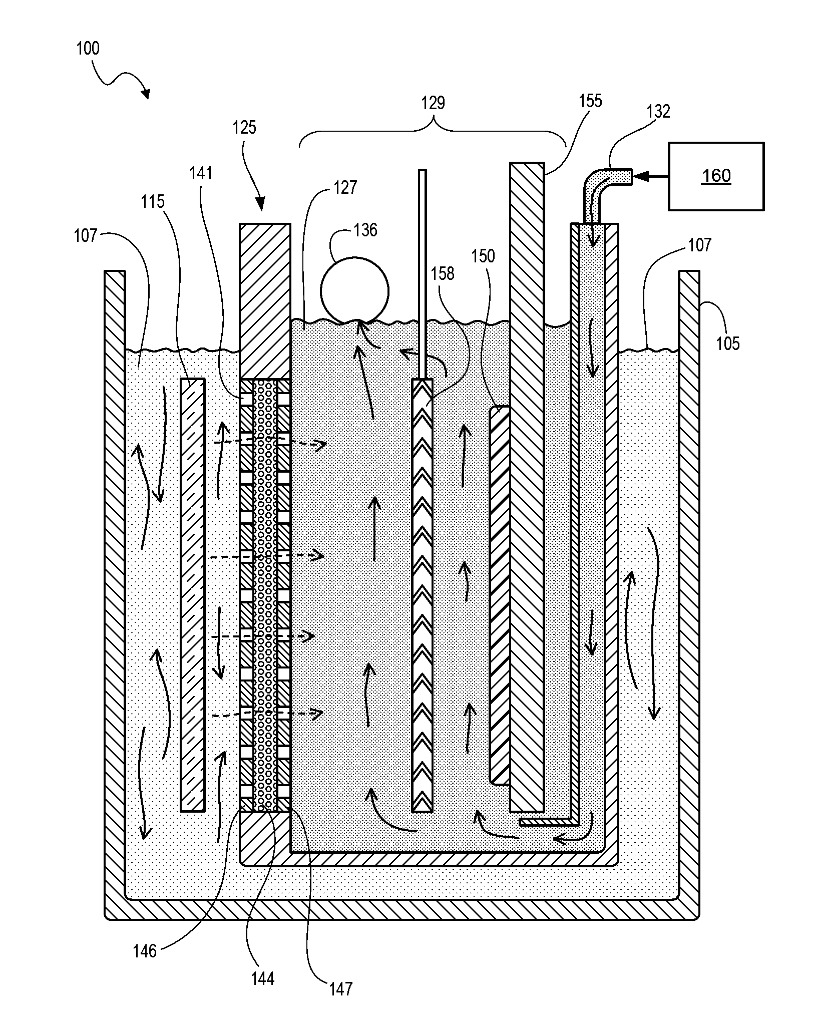
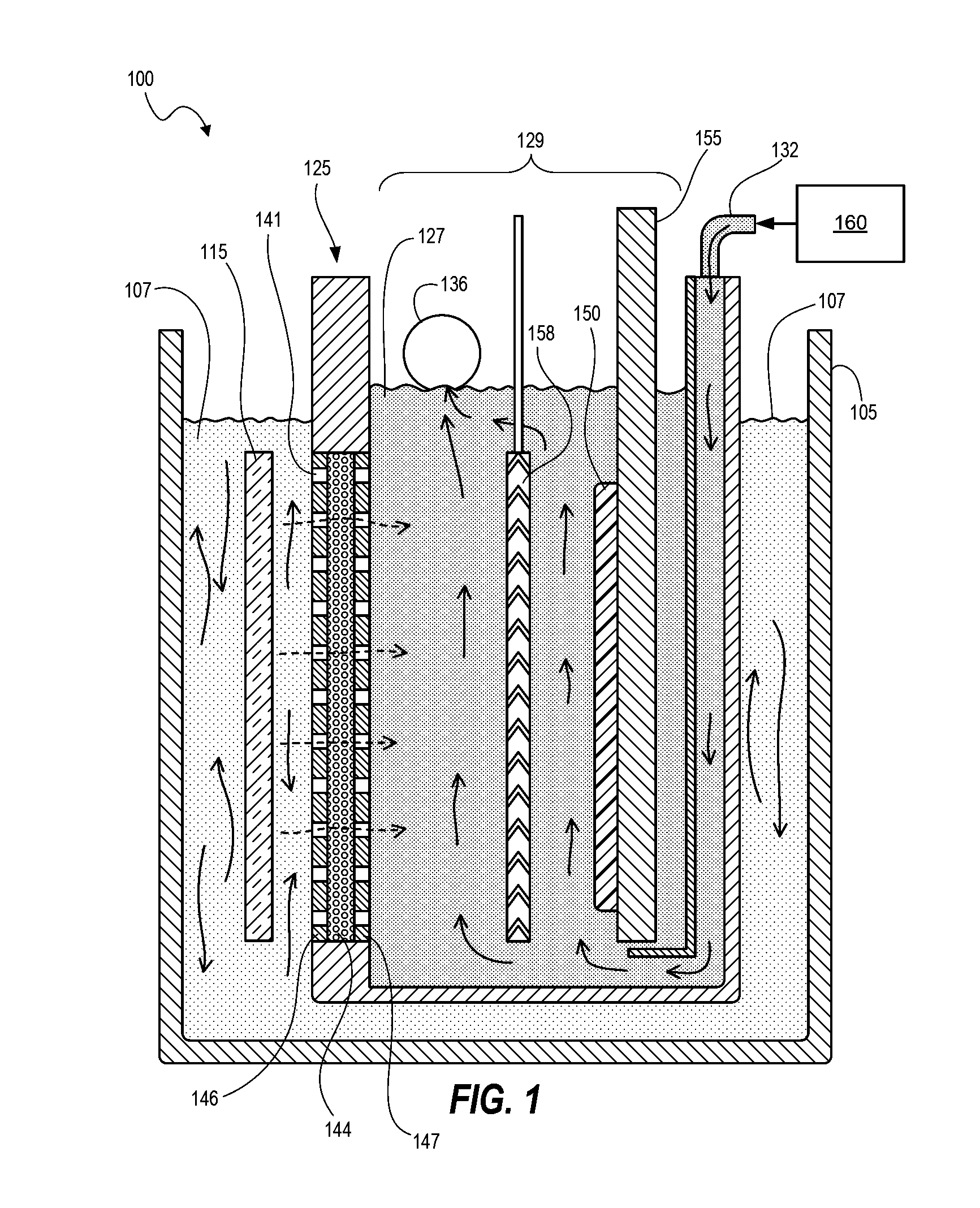
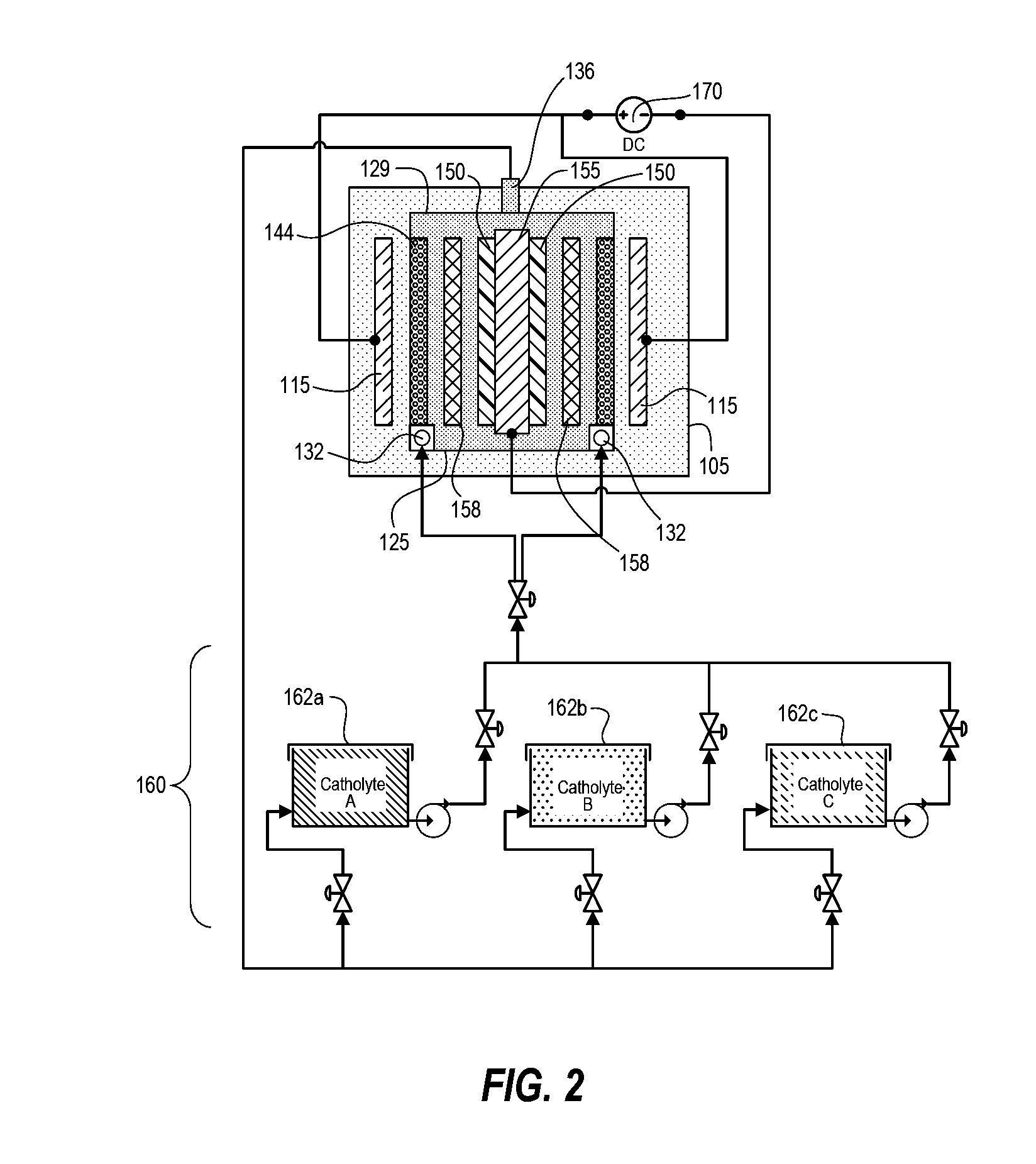
[0020]Techniques disclosed herein include an electro-chemical deposition apparatus that provides a simplified circulation system, better chemical management for more reliable and uniform plating, as well as short maintenance times for greater tool availability. Techniques include a processing tank containing an anolyte fluid, and one or more plating cells each having a catholyte fluid compartment having a circulation path that connects to a separate or remote catholyte reservoir. The anolyte fluid is not the process electrolyte and needs substantially less maintenance as compared to the catholyte fluid that needs constant replenishment of metal ions and other additives. Thus, with such a configuration as disclosed herein, a single pump can be used to flow catholyte (via manifolds) through one or more plating cells. The anolyte fluid in the processing tank can circulate via inherent fluid diffusion, or the apparatus can include an optional flow mechanism in the processing tank such a...


PUM

PropertyMeasurementUnit
timeaaaaaaaaaa
distanceaaaaaaaaaa
currentaaaaaaaaaa

Abstract

Techniques disclosed herein include an electro-chemical deposition apparatus that provides an efficient circulation system, chemical management that provides reliable and uniform plating, and a configuration that provides short maintenance times and greater tool availability. Techniques include a processing tank containing an anolyte fluid, and one or more plating cells each having a catholyte fluid compartment with a circulation path that connects to a separate or remote catholyte reservoir. Thus, with such a configuration, a single pump can be used to flow catholyte (via manifolds) through one or more plating cells. Thus, with the catholyte reservoir maintained off board, instead of dumping catholyte over a weir into a reservoir, catholyte fluid—after flowing through a plating cell—is returned to the catholyte reservoir.

Description

BACKGROUND OF THE INVENTION[0001]This invention relates to methods and systems for electro-chemical deposition including electroplating of semiconductor substrates.[0002]Electro-chemical deposition, among other processes, is used as a manufacturing technique for the application of films to various structures and surfaces, such as to semiconductor wafers and silicon work pieces or substrates. Such films can include tin silver, nickel, copper or other metal layers. Electro-chemical deposition involves positioning a substrate within a solution that includes metal ions, and then applying an electrical current to cause metal ions from the solution to be deposited on the substrate. Typically, electrical current flows between two electrodes, namely, between a cathode and an anode. When a substrate is used as the cathode, metal can be deposited thereon. A plating solution can include one or more metal ion types, acids, chelating agents, complexing agents, and any of several other types of a...

Claims


Application Information

Patent Timeline
Patent Type & Authority Patents(United States)
IPC IPC(8): C25D21/10C25D17/10H01L21/288C25D21/14C25D17/06C25D7/12C25D17/00
CPCC25D17/001C25D17/002C25D17/06C25D17/10C25D21/14H01L21/2885C25D21/10
Inventor KEIGLER, ARTHURGUARNACCIA, DAVIDPAPAPANAYIOTOU, DEMETRIUSHANDER, JONATHAN
Owner ASMPT NEXX INC
Why Eureka
Try Eureka