In situ retorting of hydrocarbons
a hydrocarbon and in situ technology, applied in the field of in situ retorting of hydrocarbons, can solve the problems of reducing the relative permeability of the formation, affecting the fluid flow of materials, and largely failing the practicality test of work
- Summary
- Abstract
- Description
- Claims
- Application Information
AI Technical Summary
Benefits of technology
Problems solved by technology
Method used
Image
Examples
example 1
Identification of Several Oil Shale Resource for Development Using the Systems and Methods of this Invention
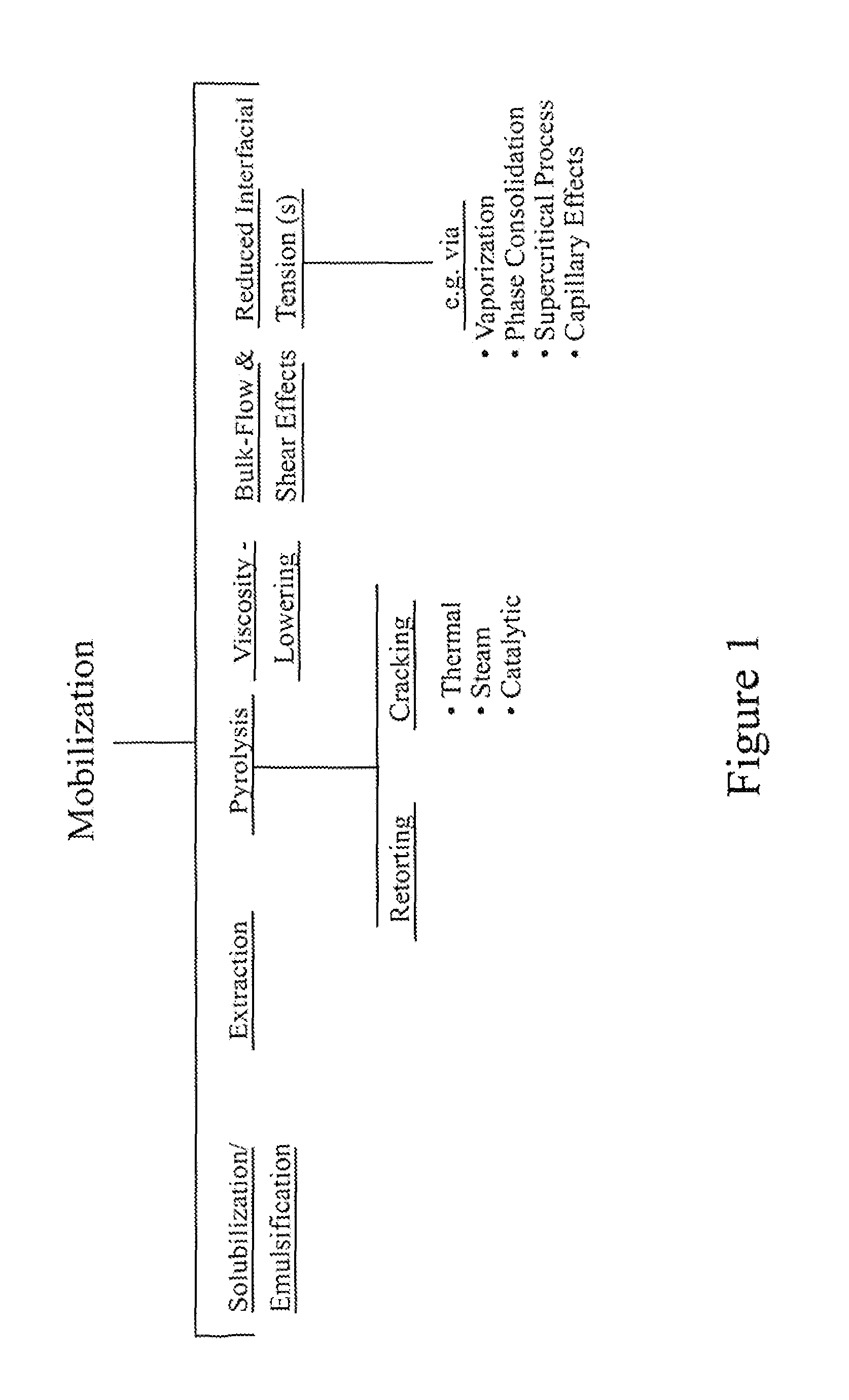
[0099]Hydrodynamically-modulated, in-situ retorting of oil shale and other hydrocarbon formations may be conducted using the methods of this invention. In an embodiment, successful retorting of an oil shale formation may be accomplished while simultaneously protecting surrounding formation water from leakage of fluids from the retort-treated portion of the formation. In one embodiment, surrounding aquifers may be protected using hydrodynamic-flow barriers. Use of such containment methods are preferred in areas where the natural aquifers' potentiometric surface is at least 200 ft higher than the elevation of the aquifers in the target formation. To this end, preferred, oil shale resource area selected for in situ retorting and / or treatments comprising this invention are those containing high-permeability, natural aquifers through which thermal-energy carrier fluid (TECF) may be...
example 2
Characterization and Development of a Carbonaceous Oil Shale Formation Exemplified in the Piceance Basin of Colorado
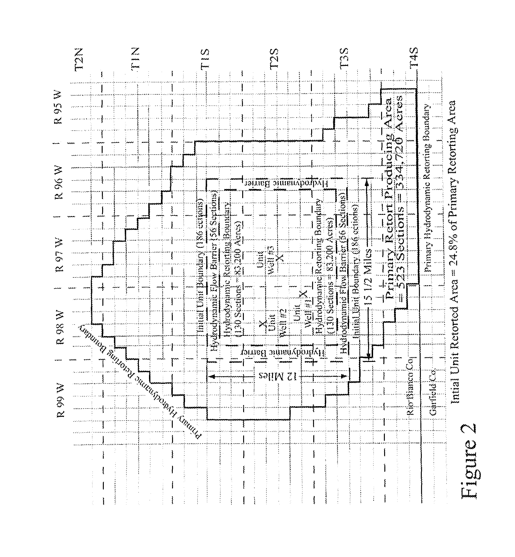
[0105]In a specific embodiment, the methods of this invention are applied to the development and in situ retorting of the oil shale formation in the Piceance Basin. As shown in FIG. 2, a preferred portion of the basin is located substantially within Rio Blanco County Colorado, between coordinates ranging from R 99 W-to-R 95 W, and T 2 N-to-T 4 S. FIG. 1 illustrates an approximately 12 mile by 15½ mile segment of this basin representing the core unitized (e.g. target) area for application of this in situ retorting method. As shown in the FIG. 1 (inner-most dashed box), this target area comprises approximately 130 sections, or about 83,200 acres. This propped, unitized, active retort area is surrounded by a hydrodynamic barrier (shown as the outer-most dashed box) comprising about an additional 56 sections, of the resource area. Within the unitized retort area, proposed ...
example 3
Mobilization of Hydrocarbon and Other Materials from Various Lithologic Layers
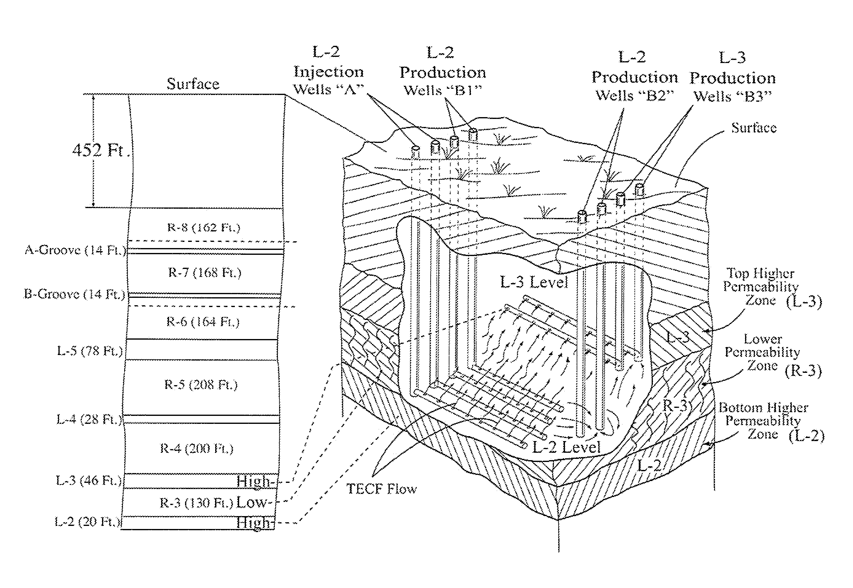
[0117]FIG. 5 illustrates the approximate stratigraphic column of the oil-shale zone as typically occurring at locations near the center and deeper portion of the Piceance Basin (i.e., Sect. 36, T2 S, R98W). A cross-section of the formation showing depths and thicknesses of various deposits is shown on the left of FIG. 5. An expanded view of the portion of the formation (e.g. depths of about 590 ft to about 840 ft) containing the A-Groove, B-Groove and R-7 stratigraphic zone is shown on the right. The zones labeled R-8, R-7, R-6, R-5, R-4, R-3, etc. are relatively rich zones containing relatively large quantities of kerogen and relatively small amounts of porous zones or “voids” (open holes) left in the rock after the soluble minerals have been dissolved by hydrodynamically flowing formation water. Consequently, these “R”-designated (i.e., “R-rated”), oil-shale zones have relatively few aquifers, and any ex...
PUM
 Abstract
Description
Claims
Application Information
 - R&D
- Intellectual Property
- Life Sciences
- Materials
- Tech Scout
- Unparalleled Data Quality
- Higher Quality Content
- 60% Fewer Hallucinations
Browse by: Latest US Patents, China's latest patents, Technical Efficacy Thesaurus, Application Domain, Technology Topic, Popular Technical Reports.
© 2025 PatSnap. All rights reserved.Legal|Privacy policy|Modern Slavery Act Transparency Statement|Sitemap|About US| Contact US: help@patsnap.com


