Coating and curing apparatus and methods

Active Publication Date: 2016-04-19
FIRST SOLAR INC (US)
View PDF25 Cites 13 Cited by
  • Summary
  • Abstract
  • Description
  • Claims
  • Application Information

AI Technical Summary

Benefits of technology

[0019]In some embodiments, the curing facility includes at least one heat applicator such as a roller or a plate that directly contacts the substantially flat substrate and heats the surface by direct conduction. The heat applicator may be composed of metals including iron, steel, stainless steel, aluminum, copper, brass and other alloys. The metal selected should exhibit at least one of good heat capacity, hardness and wear resistance, reasonable corrosion resistance, low cost and good machinability. The heat applicator may be a composite structure wherein a core of material, such as for example, copper or the like is encased in a secondary material to impart additional properties such as corrosion resistance or compliance, or enhanced wear resistance. The outer coating material may be a polymer engineered to withstand high temperatures, such as a silicone rubber or the like. The heat applicator may also include ceramic or refractory materials entirely or in part. The applicator may be heated using an electrical heating element incorporated into the applicator, or by passing a heated gas or liquid through one or more channels inside the applicator, or by direct heating on the outer surface of the applicator using electrical heating or direct heating by combustion of a fuel such as gas jets or the like. In an embodiment where the heat applicator is at least one roller, the heated roller may contact the coated surface of the substantially flat substrate and directly heats the coating by thermal conduction. In some embodiments, additional heated rollers may contact the coated surface of the substantially flat substrate sequentially such that each heated roller provides additional heating to raise the temperature of the coating to the desired value. In some embodiments, additional

Problems solved by technology

There are several well documented techniques for applying wet sol to substrates, some of which are in widespread industry use and others that have generally been limited to the laboratory.
These methods may or may not work in concert with components of the coating that catalyze or otherwise aid the curing process.
This can be advantageous if complete sol coverage is desired but is disadvantageous if the coating on some portion of the substrate interferes with a later substrate processing step.
The dip coating technique requires a tank slightly larger than the substrate, which for large substrates means the tank may hold a large volume of sol.
For sols m

Method used


Image

  • Coating and curing apparatus and methods
  • Coating and curing apparatus and methods
  • Coating and curing apparatus and methods

Examples


Embodiment Construction

[0044]Various embodiments of the disclosure are described below in conjunction with the Figures; however, this description should not be viewed as limiting the scope of the present disclosure. Rather, it should be considered as exemplary of various embodiments that fall within the scope of the present disclosure as defined by the claims. Further, it should also be appreciated that references to “the disclosure” or “the present disclosure” should not be construed as meaning that the description is directed to only one embodiment or that every embodiment must contain a given feature described in connection with a particular embodiment or described in connection with the use of such phrases. In fact, various embodiments with common and differing features are described herein.

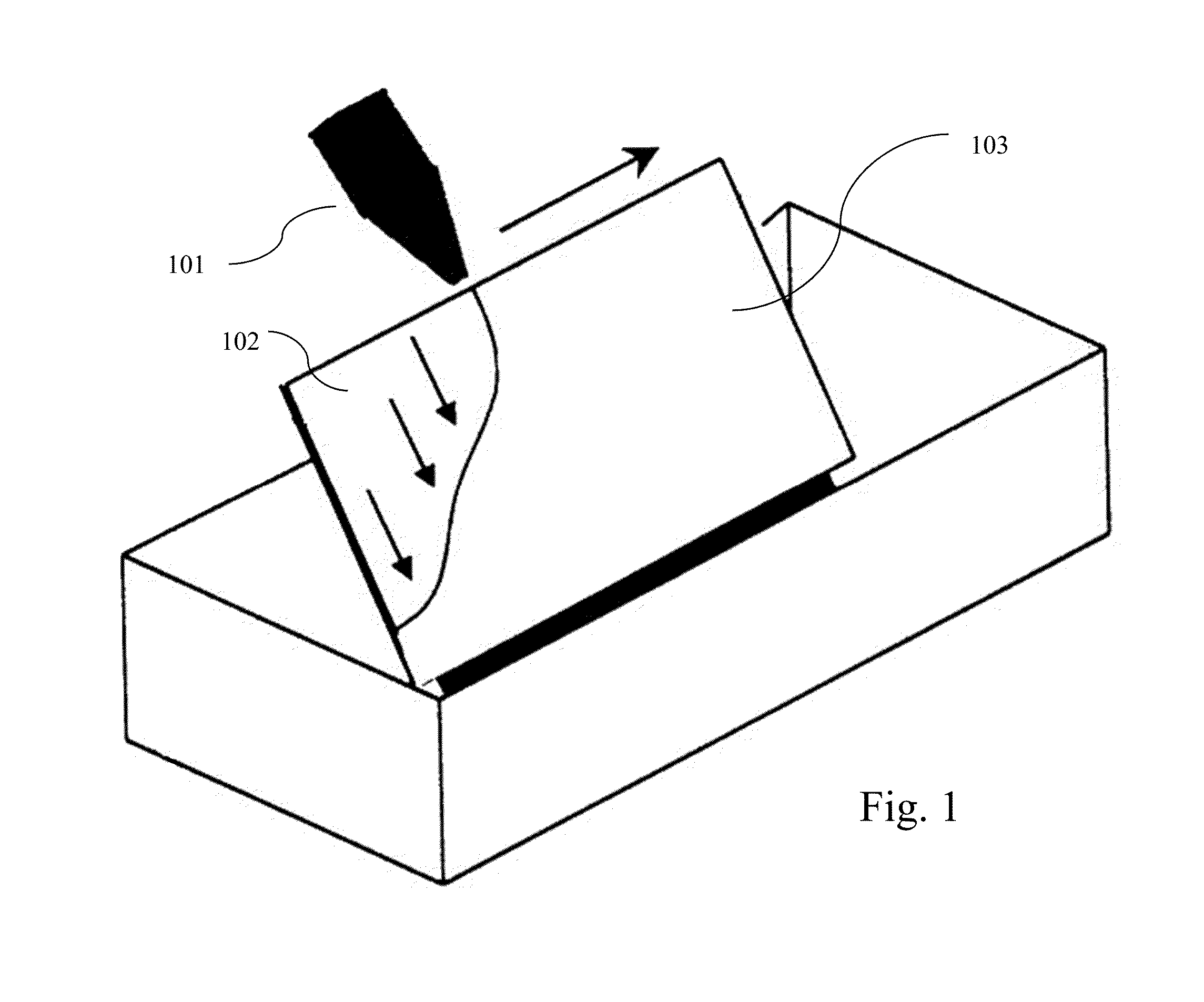
[0045]FIG. 1 depicts an embodiment of laboratory scale flow coating. In embodiments, a nozzle (101) dispenses a material (102) onto an inclined substrate (103) as it is moved across the top edge of the substrate. T...


PUM

PropertyMeasurementUnit
Temperatureaaaaaaaaaa

Abstract

Disclosed is a coating apparatus including flow coating and roll-coating that may be used for uniform sol-gel coating of substrates such as glass, solar panels, windows or part of an electronic display. Also disclosed are methods for substrate preparation, flow coating and roll coating. Lastly, systems and methods for curing sol-gel coatings deposited onto the surface of glass substrates using high temperature air-knives, infrared emitters and direct heat applicators are disclosed.

Description

STATEMENT REGARDING GOVERNMENT FUNDING[0001]This invention was made with government support under Contract DE-EE0006810 awarded by the U.S. Department of Energy. The government has certain rights in the invention.BACKGROUND[0002]1. Field[0003]The present disclosure relates generally to the field of thin-film sol-gel coatings and in particular to coating on substrates such as glass or solar panels.[0004]2. Description of Related Art[0005]Thin-film sol-gel coating refers to a technique of coating substrates, such as optical surfaces, windows, solar panel surfaces, and the like, using a wet chemical formulation called a ‘sol’ that undergoes a ‘gelation’ process wherein it polymerizes to form a solid thin-film on a substrate. These thin-films often undergo a subsequent curing step to increase mechanical strength and other properties. This curing is often accomplished by heating or irradiating the substrate and coating. Thin-film sol-gel coating is a very versatile process that has many ...

Claims


Application Information

Patent Timeline
IPC IPC(8): B05C1/08B05C11/10B05C9/14B05C11/02
CPCB05C9/14B05C11/025B05C1/08B05C11/1005B05C1/0817B05C1/083B05C1/0856B05C1/0865B05C5/007B05C5/0254B05C11/08B05C11/1039C23C18/1254C23C18/22H01L31/18H01L31/00
Inventor BROPHY, BRENOR L.GONSALVES, PETER R.MAGHSOODI, SINACOLSON, THOMAS E.YANG, YU S.ABRAMS, ZE'EV R.
Owner FIRST SOLAR INC (US)
Why Eureka
Try Eureka