Coil component

a technology of components and coils, applied in the direction of transformers/inductance details, inductances with magnetic cores, inductances, etc., can solve problems such as the possibility of cracking of external resins, and achieve excellent heat-resistance reliability

Active Publication Date: 2016-04-19
MURATA MFG CO LTD
View PDF13 Cites 0 Cited by
  • Summary
  • Abstract
  • Description
  • Claims
  • Application Information

AI Technical Summary

Benefits of technology

[0006]Therefore, a main object of the present invention is to provide a coil component which has extremely excellent heat-resistance reliability.

Problems solved by technology

More specifically, as the temperature range is wider, the influence of the difference in linear expansion coefficient between the core and the exterior resin is increased to increase the stress generated when the exterior resin is cured or when the coil component is used, and make the exterior resin likely to be cracked.

Method used


Image

  • Coil component
  • Coil component
  • Coil component

Examples


experimental example

[0042]The coil component according to the present invention was evaluated in terms of heat-resistance reliability.

[0043]Coil components according to the present invention were obtained in accordance with Examples 1 to 11 described below. In addition, coil components for comparison with the coil components according to the present invention were obtained in accordance with Comparative Examples 1 to 7.

example 1

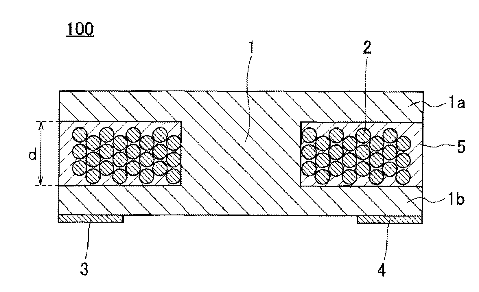
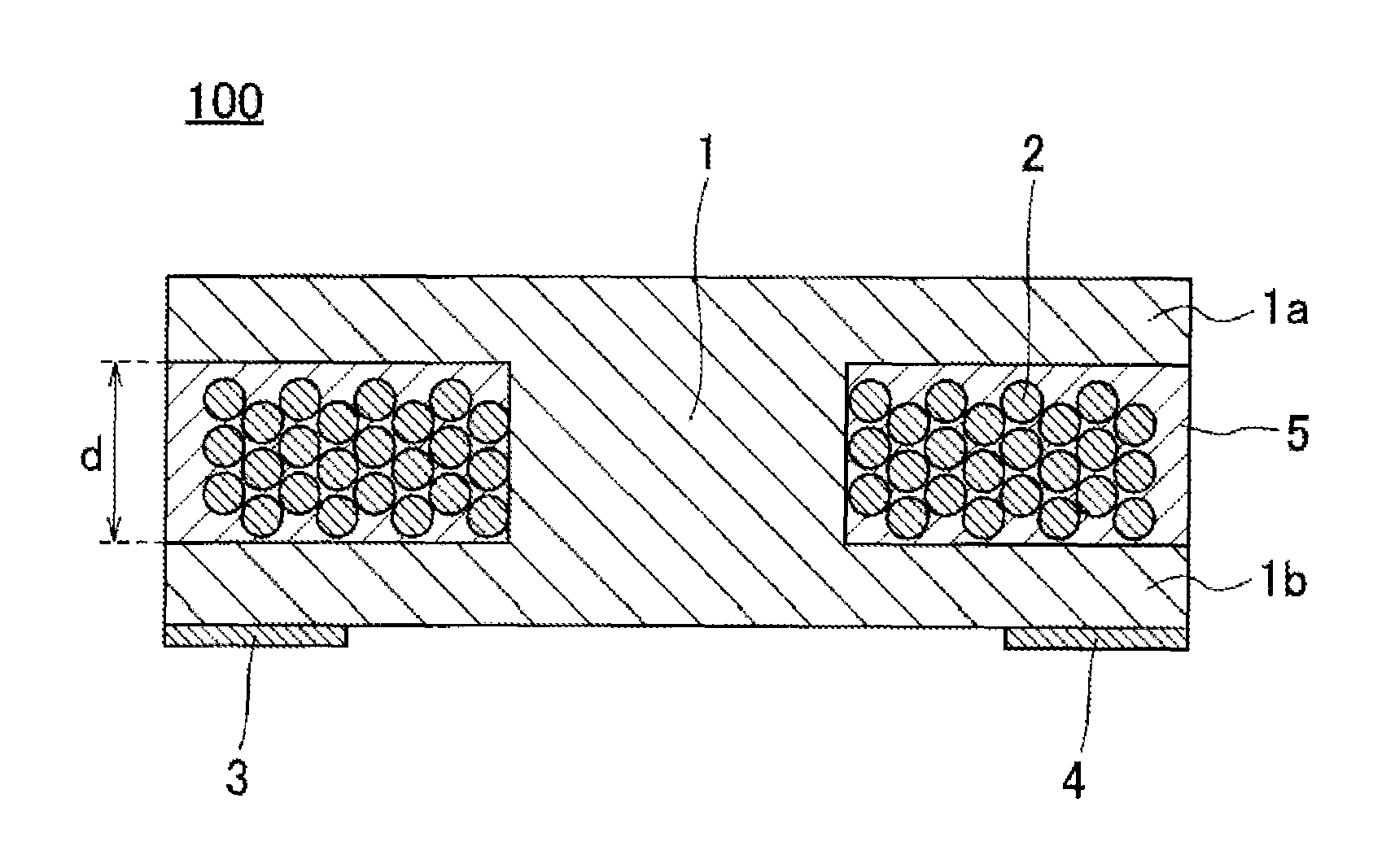
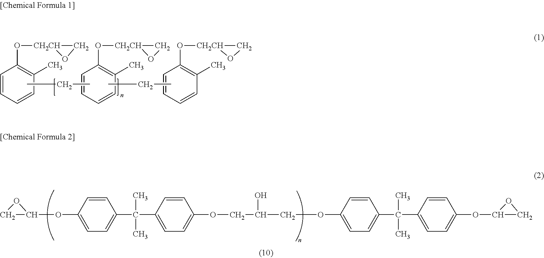
[0044]Mixed were: 662.7 g of ferrite (D50=0.6 μm) and 139.5 g of spherical silica (D50=8 μm) as an inorganic filler; 17.8 g of cresol novolac-type epoxy resin (epoxy equivalent 218) as an epoxy resin; 8.7 g of phenolic resin as a curing agent; 6.5 g of phenoxy resin (MW=50,000); 155.1 g of dipropylene methyl ether acetate as a solvent; 0.3 g of an imidazole-based curing accelerator; 6.4 g of a dispersant; and 3.0 g of a coupling agent, for obtaining an exterior resin. The same solvent was added to the obtained exterior resin to attenuate the viscosity to approximately 1 Pa·s, and the resin was applied to a copper wire-wound drum-shaped ferrite core with flange spacing of 0.85 mm with the use of a dispenser (inside nozzle diameter: 250 μm), and subjected to drying at 80° C., and curing at 150° C. to obtain a coil component. Through the compounding as described above, the proportions of the inorganic filler and phenoxy resin to the exterior resin are respectively 95 mass % and 0.8 mas...

example 2

[0045]Except for the application to a copper wire-wound drum-shaped ferrite core with flange spacing of 0.32 mm, a coil component was obtained in the same way as in Example 1. Through the compounding as described above, the proportions of the inorganic filler and phenoxy resin to the exterior resin are respectively 95 mass % and 0.8 mass %, and the mass ratio between the epoxy resin and the phenoxy resin is epoxy resin:phenoxy resin=73:27.


PUM

PropertyMeasurementUnit
spacing distanceaaaaaaaaaa
mass %aaaaaaaaaa
storage elastic modulusaaaaaaaaaa

Abstract

A coil component that includes a drum-shaped core with an upper flange and a lower flange, a winding wound around the core, and an exterior resin between the upper flange and lower flange of the core. The exterior resin includes an inorganic filler at 91 to 95 mass % with respect to the exterior resin, and a resin that has more than one glass transition temperature and has a phase-separated structure. A flange spacing distance between the upper flange and the lower flange is 1.0 mm or less.

Description

CROSS REFERENCE TO RELATED APPLICATIONS[0001]The present application is a continuation of International application No. PCT / JP2013 / 056953, filed Mar. 13, 2013, which claims priority to Japanese Patent Application No. 2012-076688, filed Mar. 29, 2012, the entire contents of each of which are incorporated herein by reference.FIELD OF THE INVENTION[0002]The present invention relates to a coil component for use in various types of electronic devices, and more particularly, to a coil component including a drum-shaped core, a winding wound around the core, and an exterior resin formed between an upper flange and a lower flange of the core.BACKGROUND OF THE INVENTION[0003]Coil components including a drum-shaped core, a winding wound around the core, and an exterior resin formed between an upper flange and a lower flange of the core have been known as coil components for use in electronic devices. For example, Japanese Patent Application Laid-Open No. 2010-16217 (Patent Document 1) disclose...

Claims


Application Information

Patent Timeline
Patent Type & Authority Patents(United States)
IPC IPC(8): H01F27/24H01F27/255H01F27/29H01F27/32H01F27/28H01F17/04H01F3/10
CPCH01F27/2876H01F17/045H01F27/255H01F27/29H01F27/327H01F2003/106
Inventor MASAKI, HIROYUKIKINAMI, NOBUYUKIMARUSAWA, HIROSHI
Owner MURATA MFG CO LTD
Why Eureka
Try Eureka