Magnetic logic unit (MLU) cell and amplifier having a linear magnetic signal

a logic unit and linear technology, applied in the field of linear magnetic signal amplifiers, can solve the problems of extremely small feed forward coupling capacitance between input and output, extremely low gain of each three-terminal mram cell, etc., to maximize linearity and/or tmr, the effect of extended cut off frequency

Active Publication Date: 2016-04-26
CROCUS TECHNOLOGY
View PDF9 Cites 0 Cited by
  • Summary
  • Abstract
  • Description
  • Claims
  • Application Information

AI Technical Summary

Benefits of technology

[0016]The disclosed MLU amplifier has large gains and extended cut off frequencies. The MLU amplifier maximizes the linearity and / or the TMR.

Problems solved by technology

However, the gain of each three-terminal MRAM cell is extremely low; the feed forward coupling capacitance between input and output is remarkably tiny.

Method used


Image

  • Magnetic logic unit (MLU) cell and amplifier having a linear magnetic signal
  • Magnetic logic unit (MLU) cell and amplifier having a linear magnetic signal
  • Magnetic logic unit (MLU) cell and amplifier having a linear magnetic signal

Examples


Embodiment Construction

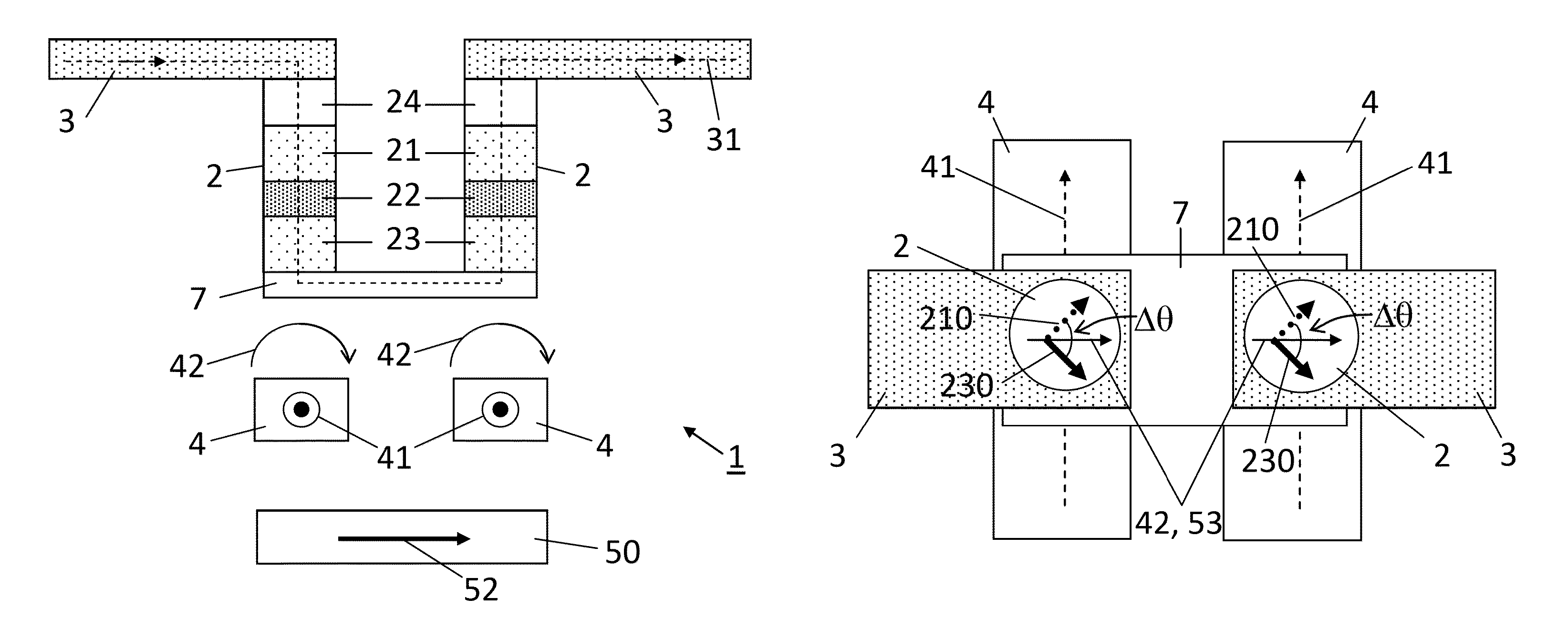
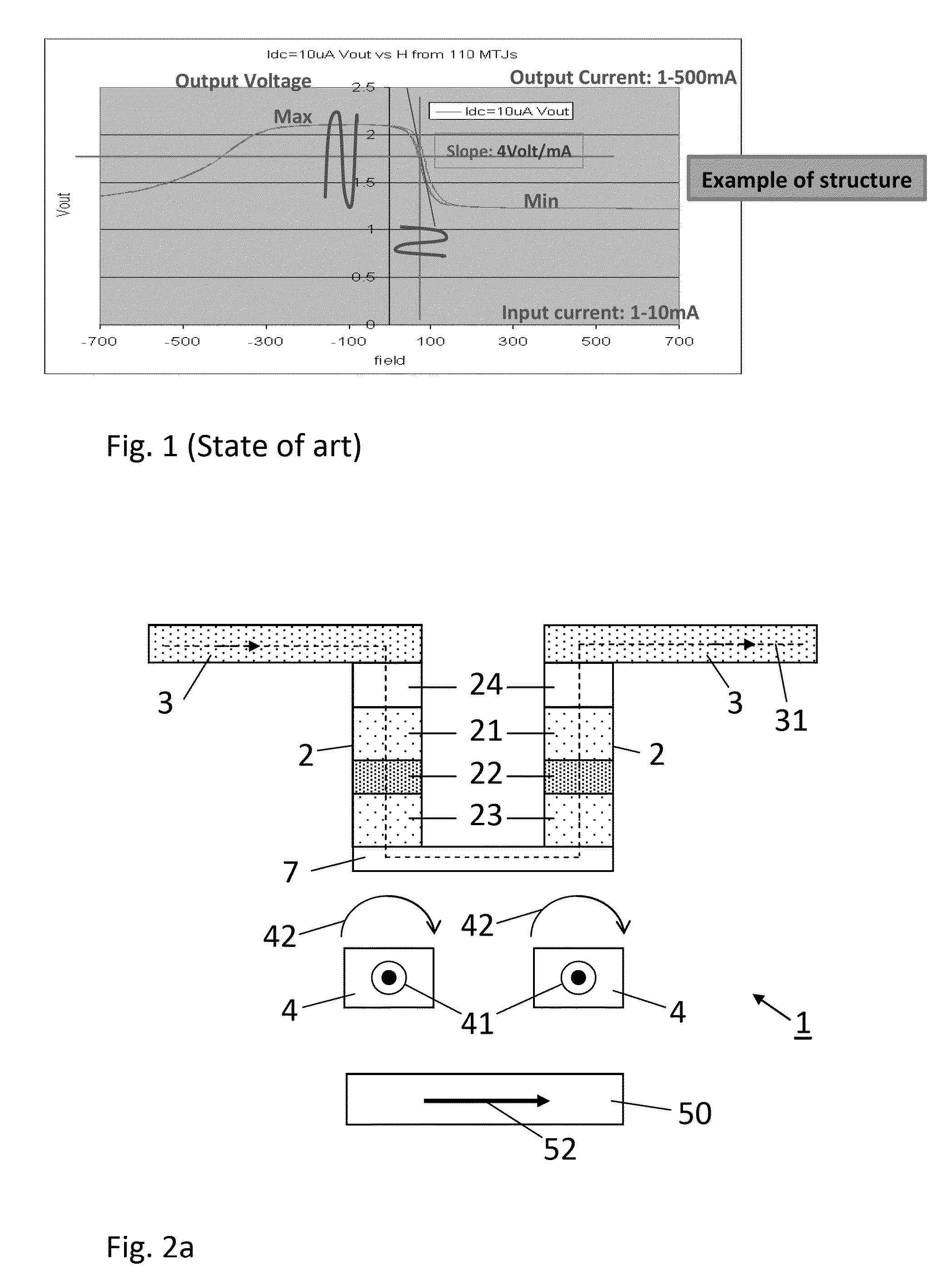
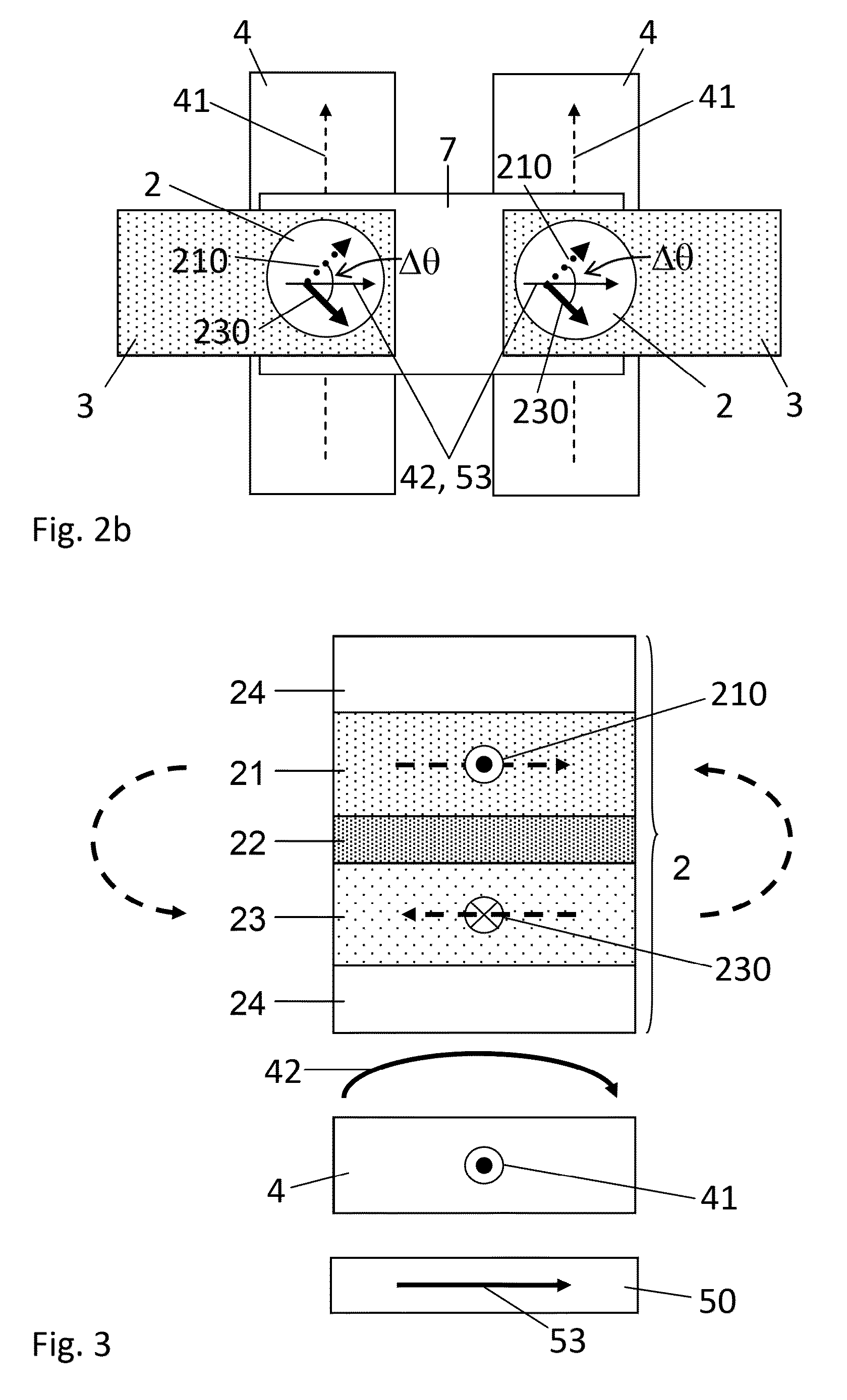
[0028]FIG. 2 shows a cross section view (a) and a top view (b) of an MLU cell 1 according to an embodiment. The MLU cell 1 comprises a first and second magnetic tunnel junction 2, each of the two magnetic tunnel junctions 2 being electrically connected in series at one end via an electrically conductive strap 7. A current line 3 is electrically connected to the other end of the magnetic tunnel junctions 2. The current line 3 can be used to pass a heating current during a write operation or a read current during a read operation. The MLU cell 1 further comprises a field line 4 arranged for passing a field current 41 such as to generate an external magnetic field 42. In the example of FIG. 2, the field line 4 is represented as two parallel field line portions 4′ located at the end of the magnetic tunnel junctions 2 connecting the strap 7. The field line 4 (or each of the field line portions 4′) can preferably comprise a cladding.

[0029]FIG. 3 illustrates one of the magnetic tunnel junc...


PUM


Abstract

A magnetic logic unit (MLU) cell includes a first and second magnetic tunnel junction, each including a first magnetic layer having a first magnetization, a second magnetic layer having a second magnetization, and a barrier layer; and a field line for passing a field current such as to generate an external magnetic field adapted to adjust the first magnetization. The first and second magnetic layers and the barrier layer are arranged such that the first magnetization is magnetically coupled antiparallel with the second magnetization through the barrier layer. The MLU cell also includes a biasing device arranged for applying a static biasing magnetic field oriented substantially parallel to the external magnetic field such as to orient the first magnetization at about 90° relative to the second magnetization, the first and second magnetizations being oriented symmetrically relative to the direction of the external magnetic field.

Description

FIELD[0001]The present invention concerns a magnetic logic unit (MLU) cell based on MRAM technology having a linear magnetic signal. The present invention further concerns a MLU amplifier comprising a plurality of the MLU cell.DESCRIPTION OF RELATED ART[0002]A conventional MRAM cell comprises a magnetic tunnel junction comprising a ferromagnetic reference layer and a ferromagnetic storage layer. When the magnetizations of the two layers are aligned the resistance of the stack is low, this could be a “0” (or arbitrarily a “1”). When the layers are anti-aligned the resistance is high, this could be a “1” (or vice versa).[0003]In thermally-assisted-switching (TAS) MRAM's the storage layer is blocked by an antiferromagnetic layer such as to achieve superior stability in normal operating temperatures. During a programming cycle, the temperature of the cell is momentarily locally raised above a blocking temperature of the antiferromagnetic layer, through resistive heating of the magnetic ...

Claims


Application Information

Patent Timeline
Patent Type & Authority Patents(United States)
IPC IPC(8): H01L43/00H01L29/82H01L43/02H03K19/18H01L43/10G11C11/16H03F15/00
CPCH03F15/00G11C11/16G11C11/1675H01L43/02H01L43/10H03K19/18H10N50/80H10N50/85
Inventor PREJBEANU, IOAN LUCIANDIENY, BERNARDMACKAY, KENNETHCAMBOU, BERTRAND
Owner CROCUS TECHNOLOGY
Why Eureka
Try Eureka